Download
1 / 27
300 likes | 598 Vues
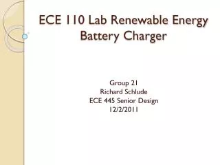
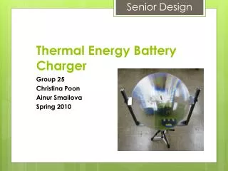
Thermal Energy Battery Charger. Group 25 Christina Poon Ainur Smailova Spring 2010. Introduction. What Are We Making? What Does It Do? What Can You Use It For?. Overview. Solar Collector Array. Design Considerations. 22.5” Fresnel lens 28” focal length Max temp. = 565F

E N D
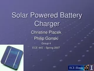
Thermal Energy Battery Charger Group 25 Christina Poon Ainur Smailova Spring 2010
Introduction • What Are We Making? • What Does It Do? • What Can You Use It For?
Design Considerations • 22.5” Fresnel lens • 28” focal length • Max temp. = 565F • Adjustable tilt angle • Normal to sun • Tripod
Thermoelectric Generator Module • VT-127-1.4-1.5-71 • Max Temp: 392F • Max diff: 176F
Efficiency 6%
Optimization • Heat Transfer Blocks • Black anodized aluminum • Bare aluminum • Heat Sink • Aluminum stampings • Water bin • Efficiency: .49%
Zetex ZXLB1600 • Input voltage range: 1.6 – 5.5V • Adjustable output up to 28V • Voltage adjustment by external resistors • Cheap • Reliable • Minimal parts required • 80% efficiency
Testing/Verification Min input = 1.4V Max input = 5.5V
Components • Input voltage: 2.0-5.5V • LM317 – Current regulator • Maintains 1.2V
Current Optimization 93.35 mA 89.37 mA On
DS2715 • Charges 1 to 10 NiMH cells • Regulates current through linear control • Adjustable charging time • Safety regulations: over-temperature, over-voltage protection • Time-out selection
Testing – Current Regulation Min. output current
DS2715 vs. PIC16C711 • Load current • Input voltage threshold • Price
Successes • Met design goals • Reliable charging current • 89.3mA → 22.4hrs • Boost converter outputs reliable value • 2.2% tolerance • TEG system produces adequate power to meet circuit needs
Further Improvements • Improved power generation • Multiple modules • Running water • Heat storage • Container to prevent radiation from heat transfer block • Could charge multiple/larger batteries with enough power
Acknowledgements • ECE Machine Shop (Scott McDonald, David Switzer, Greg Bennet) • ECE Parts Shop (Mark Smart) • Power Lab (Kevin Colravy) • Tom Galvin • Prof. Paul S. Carney