Download
1 / 44
440 likes | 806 Vues

E N D
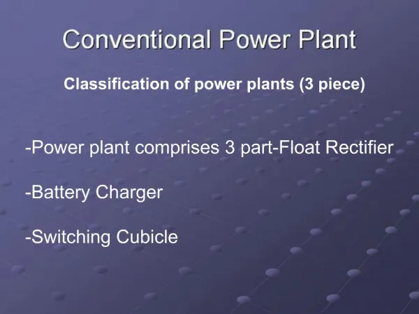
3. Another classification of power plant is Single unit type Two unit Type Three unit type
F.R,B.C and -One unit is FC/BC/SWC -FR, BC, and SC are
SC will be in (Float rectifier cum in individual units.
Single container battery charger, cum
Switching cubicle )
Ex: 5/12A PP - another unit is FR
4. Nowadays mostly 2 units p/p are used with maintenance free batteries and all transmission power plant are 2-unit type only. The latest being P/P of SMPS with VRLA batteries
5. Working Principle of con. PP
7. Step Down
8.
Rectification
Any unidirectional device rectifies the AC to DC.
Here Diodes & SCRs are used for rectification.
9. Filtering
Here multi-stage L.C. Filters are used for filtering the A.C. Ripples
10. Regulation
As far as Float Rectifier is concerned,
�Regulation is the mechanism by which the output of a float rectifier is kept constant at 51.5 _+0.5V irrespective of input voltage variations of ? 12%. Output load variations of 5% to 105% and input frequency variations of ? 4% or 48-52 Hz�.
11. Why Regulation is required?
Float rectifier should not only supply power to the load but also takes care of its battery sets , which are floated across its output .
If the float rectifier output voltage is 51.5v, the cells are floated at 2.15v/cell and hence they are continuously trickle charged and this compensates losses due to �self discharge or local action�.
12. Why Regulation is required?..
13. If FR output is <49.0V, the battery starts discharging.
If FR output >51.5, the floating voltage of each cell will be > 2.15V and the battery will be over charged.
Hence regulation is required.
14. How is regulation done?
15. Transductor Method
Normally this principle is used in small exchange power plants.
In this a transductor is placed in series with the rectifier and uses the principle that the impedance of an iron cored coil can be varied by varying the degree of saturation of the core.
By varying the series impedance to rectifier, we can vary the portion of input cycle that is fed to Rectifier.
16. Transductor Method
By SCR method
SMPS method
17. Transductor Method
Normally this principle is used in small exchange power plants.
In this a transductor is placed in series with the rectifier and uses the principle that the impedance of an iron cored coil can be varied by varying the degree of saturation of the core.�
By varying the series impedance to rectifier, we can vary the portion of input cycle that is fed to Rectifier
18. SCR Method
20. SCR can be switched on by applying the positive pulse to the gate. Once if the SCR is switched on, it will be in �ON� condition as long as the current flowing through SCR is above a threshold value called �Holding current�.
21. SCR regulation
In a Float rectifier, across each half cycle one SCR is connected. Hence for 3 phases i.e. R,Y,B totally 6 SCRs connected
22. SCR regulation
23. SCR regulation
24. SCR regulation
Let an SCR is connected across the positive half cycle of a phase. The total time period of a half cycle is 10 ms. Within this half cycle triggering pulses can be given at any time. Assume that triggering pulse is given to SCR at Point�A� after 4 ms of starting of the half cycle, the SCR will be on. Even though the triggering pulse is removed, the SCR will remains on.
25. SCR regulation
But the current flowing through SCR depends on the amplitude applied across its terminals. At 9 ms i.e. @ point B let the current flowing through the SCR is just below the holding current. The SCR will be switched off. That means �switching on� of SCR is in our hands, but �swg off� of SCR is not in our hands, it is automatic. In this case the portion of half cycle between the points A and B is rectified.
26. The output voltage of the FR depends on both the input AC voltage and output DC load
29. The four main parts of a Float Rectifier are
a) 3 phase step-down transformer
b) Rectifying circuit
c) Smoothening or Filtering circuit
d) Control circuit.
30. GENERAL REQUIREMENTS Ambient conditions
Input Conditions
Cooling Arrangements
Radio Frequency Interference
Dimensions
Earthling
31. AMBIENT CONDITIONS
The float rectifiers are designed for continuous full load operation under ambient temp,(i.e. temp. Of air surrounding the cubicle) of upto 45 degree C averaged over a period of 24 hours and going to a peak of upto 50 degree C.
32. Input Conditions
For large exchange power plant, float rectifiers are designed to work from 3 phase 4 wire AC supply and are capable of giving the specified performance for nominal input voltage settings of 350,370,390,410, and 430 volts across phases and for frequency variation of ? 2 Hz from the nominal frequency of 50 Hz. For medium exchange power plant, the unit works of single phase 2 wire AC supply and is capable of giving the specified performance from nominal input voltage settings of 200,210,220,230,240v across phases and neutral. In small exchange units also the float rectifier works from single phase but no taps are used
33. Cooling Arrangements
34. Radio Frequency Interference
All source of noise are filtered if necessary with RF suppressers
The conducted radio frequency interference voltage at the input and output terminals for the entire range of input and output load conditions is kept limited to 1500 Micro volts over the frequency range from 50 KHz to 15 MHz
35.
Radio Frequency Interference
Suitable RFI Filters are provided for this purpose. The intensity of radiated RFI field at a distance of 10 metres from the power plant over the same frequency range and the input and output conditions as mentioned above is kept limited to 100 micro volts per metre and over the frequency range from 40 to 70 MHz, it shall not exceed 50 micro volts per metre
36. Radio Frequency Interference
For large exchange float rectifier, height and depth have been standardized as 200 and 120 cm respectively. For medium and small exchange units, the height and depth are 140 and 60 cm respectively
37. Functions of Battery charger.
To Initial charge a battery set:- For initial charging, the battery charger capacity should be at least 14% of AH capacity of battery set.
To normal charge the battery set at 10 hour rate.
To use as Float rectifier during emergency condition by suitable links.
To charge the sick cell.( provision exists in some power plants only).
38. O/P voltage
The O/P voltage of Battery charger can be varied from 44 V to 65 V with the help of coarse, Medium and Fine Switches in 63 steps
39. O/P Current
Battery charger can deliver 100% of its rated current up to 57 volts and above that it can deliver only 50 % of its rated capacity.
40. Components of the equipment
3 phase step-down main transformer with links for main variation and tap changing points.
Ballast chokes.
3 phase Full wave rectifier
41. Charging Current Regulation
There is no regulation in battery charger. If the input voltage varies by ?5%, there is every chance for the variation of o/p charging current by ?100%.
Example. Let us take 1000 AH Battery set.
AC I/P voltage B.C O/P voltage Battery set voltage Driving potential Bty set internal resistance Charging current440V50V47.5V2.5V2.5m?1000A+5%52.5V47.5V5.0V2.5m?2000A
In order to limit the charging current variations "Ballast chokes" are provided. Ballast chokes are provided on each phase on the secondary side of main transformer in battery charger in order to limit the charging current variations to ? 25% for the input voltage variations of ?5%.
42. 6 Alarms in Battery charger
Whenever any fault in battery charger, the alarm is extended to switching cubicle, where it will be displayed. The alarms are
Mains fail.
Phase fail.
Rectifier fuse fail.
Circuit breaker trip