Download

1 / 27
360 likes | 759 Vues
Optimizing Efficiency of Switching Mode Chargers Multi-Cell Battery Charge Management (MBCM). Outline and Purpose. Understand the key parameters of a MOSFET and the relationship to power loss of a switching charger Conduction loss Switching loss Gate drive

E N D
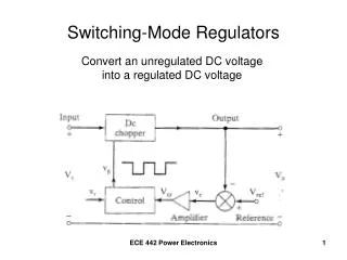
Optimizing Efficiency of Switching Mode ChargersMulti-Cell Battery Charge Management (MBCM)
Outline and Purpose • Understand the key parameters of a MOSFET and the relationship to power loss of a switching charger • Conduction loss • Switching loss • Gate drive • Inductor selection and its impact to the loss • Current sensing resistance vs. the loss • Go through the loss analysis with an existing charger EVM design
Linear Chargers VIN VBAT + ICHG Linear Charger Adapter Battery • Simple and low cost • High loss • Difference of the adaptor and battery voltage • Only for small current • - The charging current is limited due to the high loss
Advantage of Switching Chargers VIN VBAT + Battery Adapter Switching Charger • High efficiency • Wide range input voltage • High output current • High output current Need to understand the loss and optimize the efficiency
+ A Switching Charger and the Loss Components Q1 L RSNS RS1 Cin Q2 Cout Driver and Controller
Circuit under Study --- bq24715 NVDC-1 Charger L Q1 RS1 System Cin Cout bq24715 Qbat Q2 Battery Pack • Key features • NVDC-1 Charger • Extreme low quiescent current to meet Energy Star Requirement • Ultra fast transient 100us to supplement mode to prevent adaptor crash during turbo boost operation • Operation Condition • Vin=19V, Vo=8.4V, Io=6A • Fs=800KHz
MOSFET Losses Conduction Loss VDS ID VGS Switching Loss Gate driver Loss • MOSFET is equivalent to a R when it is fully on • Loss is with I-V overlapping during the On-off transition • Capacitor charge and discharge How to find the information on the DS
Rdson Dependency on the Gate Drive Voltage CSD17308Q3 • When the switch is on, it is equivalent to a resistor RDS_on. Which determines the conduction loss • RDS_onis a function of the driver voltage
Rdson Dependency on the Temp • RDS_on is a strong function of temperature. At 150oC junction temperature, the temp coefficient is around 1.4 to 1.5 • The conduction loss calculation must take the temperature coefficient into consideration
Calculation the Conduction Loss MOSFET Q1 ∆IL L IQ1 IOUT IOUT IQ2 Q1 Q2 C IQ1 D·T T • The conduction loss for Q1 and Q2 can be calculated • It starts with a assumed temperature and iteration
Gate Charge and Switching loss ID VDS Cgd VGS Rg Cds Cgs VGS(th) t QGS2 QGD QGodr QGS(th) Qsw Qgs • Qsw determines the switching loss • FOM = RDS_on x Qsw • The test condition is important
QGD is a Function of VDS Increased VDS • Qgd is a function of VDS and Qg is a function of VGS • The comparison of the Qgd should be under the same Vds conditions • Some MOSFET venders specify Qgd at low Vds, resulting in better data sheets, but not better performance
? • The test conditions are different QGD a Function of VDS • The Rdson and Qgd are similar
Find the Correct QGD • Need to use the charge graph to determine the charge under certain conditions • The charge under the same test condition is shown below (30% higher Qgd) 15V 53 13
Switching Loss Accurate Formula • Switching loss calculation assumes linear transition Lin Da 12V 0 • The voltage transitions are nonlinear, which can be included in Kv: Ig 10K Vds (5V/div) Vgs (1V/div) • Kv is about from 0.27 to 0.35 for most of the devices t1 5s/div
Gate Drive Loss L Q1 Q2 C bq24715 Gate Driver • Gate driver loss is the energy of the gate charge dissipated on the resistance of the driver loop • Gate driver loss is proportional to the gate charge and switching frequency
Body Diode Conduction Loss Vgs_Q1 Q1 t L Vgs_Q2 t Vbd Vbd_Q2 C Vds_Q2 Q2 t Ibd_Q2 ID_Q2 t tDT • The typical dead time is 20-40ns • The dead time loss impact becomes significant at high switching frequency
MOSFET Selection vs. Loss • The table above shows the loss breakdown • The selection is a tradeoff of cost and performance • The optimized design is to minimize the loss for given MOSFETS
Inductance Selection • 30% to 40% peak-to-peak current at the worst scenario • Selection Consideration • Ipeak < Inductor Isat • Low DCR • Size such as low profile • Use table in Datasheet to select
Inductor and the Loss 2525CZ 3.3uH (6.9mm x 6.5mm x 3mm) • Manufacturers provide calculation tools Core loss calculation: http://www.vishay.com/docs/34252/ihlpse.pdf
Sensing Resistor • Selection Consideration • Accuracy : requiring high value of sensing resistance • The main source of the error is the offset of the comparator • Competition needs 20mΩ sensing resistor to achieve the same accuracy • Power dissipation: requiring low value of sensing resistance
bq24715 Quiescent Current Efficiency ~80mW Q1 Q2 bq24715 System <500mW <215mW Qbat Batter Pack • Standby current • Crucial to the light load efficiency and meet the Energy Star requirement • Competition has a maximum 5mA
Loss Breakdown • The loss has a good match • The calculated loss is 2.86W • The measured loss is about 2.98W • Can be verified at different operation points Q1 Q2 IC Rsen L
Summary • MOSFET selection is based on the loss optimization and cost trade off. The loss modeling of a MOSFET is analyzed: • Conduction loss • Switching loss • Dead time loss • Gate drive • The selection of a Inductor and the tradeoff is discussed • Other loss in a charger circuit breakdown and the impact are addressed • The EVM loss breakdown is conducted