Download
1 / 48
480 likes | 546 Vues
Learn about equilibrium of particles in 2D and 3D spaces, review free-body diagrams, reactions at supports and connections, and vector components. Construct detailed free-body diagrams for solving problems effectively.

E N D
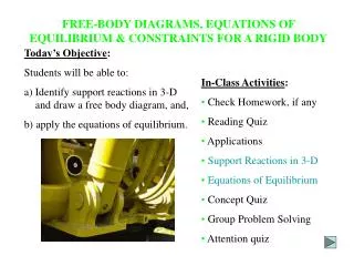
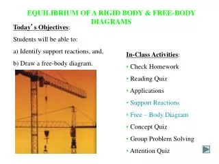
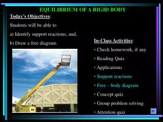
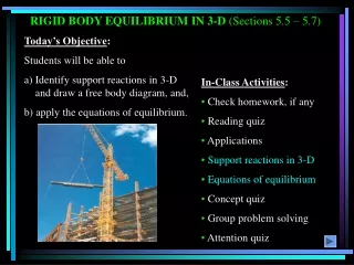
Summary • Reviewing the Free-Body Diagram • Reactions at Supports & Connections • Equilibrium of a Particle (2D and 3D spaces)
Review -Three Dimensional Vectors The vector components are written as where, i - the unit vector along the x direction j - the unit vector along the y direction k - the unit vector along the z direction
Review -Three Dimensional Vectors Vector Components: In two dimensions, a force can be described using a magnitude |F| and three angles, θx, θy, and θz. The components of the vector are Fx, Fy, and Fz.
Review -Three Dimensional Vectors Vector Components: The three angles, θx, θy, and θz are defined as:
Review - Three Dimensional Vectors Vector Components: These vector cosines are
Review - Three Dimensional Vectors Vector Components: Substitute into the vector The magnitude is |F| and unit vector is
Review -Three Dimensional Vectors Vector Components: The unit vector can be written as: The magnitude is |F| and unit vector is
Review - Resultant Forces The components of vectors are used to find the resultants acting on object. Using the unit vectors, the components of forces are
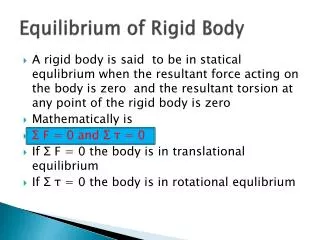
Review -Equilibrium of a Particle in Space The components of the forces in equilibrium
Free Body Diagrams The first step in solving a problem is drawing a free-body diagram (FBD). Drawing the FBD is the most crucial and important step in solving any problem. It defines weight of the body, the known external forces, and unknown external forces. It defines the constraints and the directions of the forces. If the FBD is drawn correctly the solving of the problem is trivial.
Free Body Diagrams Construction of a free body diagram. Step 1: Step 2: Step 3: Decide which body or combination of bodies are to be shown on the free-body diagram. Prepare drawing or sketch of the outline of the isolated or free body. Carefully trace around the boundary of the free-body and identify all the forces exerted by contacting or attracting bodies that were removed during isolation process.
Free Body Diagrams Construction of a free body diagram(cont.) Step 4: Choose the set of coordinate axes to be used in solving the problem and indicate their directions on the free-body diagram. Place any dimensions required for solution of the problem on the diagram.
Example Problem A 12-ft length of steel pipe weighing 600-lb is lifted by a crane cable CD. Determine the tension in cables AC and BC. 30o 30o
Example Problem Is this free body diagram going to help? FCD=600 lb This FBD is not useful for finding the tension in cables AC or CB. However, you can use it to find the tension CD which will be equal to the weight of the bar. In fact, this can be considered as the FBD of the whole ABC triangle. 30o 30o 600 lb
Example Problem 600 lbs C 30o 30o TCA TCB
FBD - Examples What is the free-body diagram of the weight?
FBD - Examples Is this free body diagram going to help? TDB TDA TDC No! The diagram should have the given angles /dimensions. W
Example Problem In a ship-unloading operation, a 3500-lb automobile is supported by a cable. A rope is tied to the cable at A and pulled in order to center the automobile over its intended position. The angle between the cable and the vertical line is 2o, while the angle between the rope and the horizontal line is 30o. What is the tension in the rope? Draw the free-body diagram.
Example Problem TAB Use the equilibrium to solve the problem 2o 30o TAC 3500lb
Example Problem Use x component to get a relationship for TAB Solve for tensions
Reactions at Supports & Connections Forces associated with joints and connections are unlike the forces we’ve been working with so far in this course. The rules for forces and moments acting at joints and contacts, will specify where the forces act; and they will specify that the forces and moments can only act along certain directions. The magnitude of the force is always unknown.
Y Fy Fx x Mz 2-D space: 3 degrees of freedom: 2 translations and one rotation Reactions at Supports & Connections Mz z Fz Fy Y Mx My x Fx In 3-D space, there are 6 degrees of freedom: 3 translations and 3 rotations
Reactions at Supports & Connections 3D Clamped, or welded joints How many degrees of freedom are restrained by this joint? This joints constrains: 3 forces & 3 Moments, all DOFs The following few slides are from Division of Engineering Brown University
Reactions at Supports & Connections 2D versions of the clamped joint Welded joint This joint constrains: 2 forces & 1 Moment (all 3 DOFs)
Reactions at Supports & Connections Pin joints How many degrees of freedom are constrained by this joint?
Reactions at Supports & Connections Pin joints This pin constrains: 3 forces & 2 Moments
Reactions at Supports & Connections 2D pinned joints 2 forces are constrained.
Reactions at Supports & Connections Roller and journal bearings, Type 1 (Bearings are used to support rotating shafts). The bearing shown is like a pin joint: it allows rotation about one axis, but prevent rotation about the other two, and prevents all relative displacement of the shaft. How many reaction forces and moments do you consider for this joint?
Reactions at Supports & Connections Roller and journal bearings, type 1 We have 3 reaction forces & 2 reaction moments
Reactions at Supports & Connections Roller and journal bearings, type 2 Some types of bearing allow the shaft both to rotate, and to slide through the bearing. How many reaction forces and moments do you consider for this joint?
Reactions at Supports & Connections Roller and journal bearings, type 2 There are 2 reaction forces & 2 reaction moments
Reactions at Supports & Connections Swivel joint Like a pinned joint, but allows rotation about two axes. How many reaction forces and moments do you consider for this joint?
Reactions at Supports & Connections Swivel joint There must be 3 components of reaction force, and 1 component of reaction moment. 3 forces & 1 Moment
Reactions at Supports & Connections Ball and socket joint Reaction forces: Prevents any relative motion. Reaction moments. Allows free rotation about all 3 axes.
Reactions at Supports & Connections Ball and socket joint There must be three components of reaction force. No reaction moments can be present. 3 forces
Reactions at Supports & Connections Slider with pin joint Allows relative motion in one direction, and allows relative rotation about one axis.
Reactions at Supports & Connections Slider with pin joint 2 forces & 2 moments
Reactions at Supports & Connections Slider with pin joint 1 force Reaction forces: Motion is prevented in two directions, but allowed in the third. There must be two components of reaction force, acting along directions of constrained motion. Reaction moments:Relative rotation is prevented about two axes, but allowed about a third. There must be two components of reaction moment.
Reactions at Supports & Connections Slider with swivel joint
Reactions at Supports & Connections Slider with swivel joint Reaction forces: Relative motion is prevented in two directions, but allowed in the third. There must be two components of reaction force acting to prevent motion. Reaction moments: Rotation is permitted around two axes, but prevented around the third. There must be one component of reaction moment. 2 forces & 1 moment
Reactions (Summary) Reaction Equivalent to a Force with Known Line of Action – Number of Unknowns = 1
Reactions (Summary) Reactions Equivalent to a Force with Unknown Direction – Number of Unknowns = 2
Reactions (Summary) Reactions Equivalent to a Force with Unknown Direction and a couple – Number of Unknowns = 3
Reactions (Summary) Reaction Equivalent to a Force with Known Line of Action – Number of Unknowns = 1
Reactions (Summary) Reaction Equivalent to a Force with Known Line of Action – Number of Unknowns = 1