Download
1 / 53
540 likes | 629 Vues
Explore electromotive force, circuits with resistors in series and parallel, and Kirchhoff's rules in this comprehensive guide. Learn how to calculate terminal voltage, power output, and equivalent resistance.

E N D
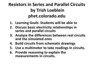
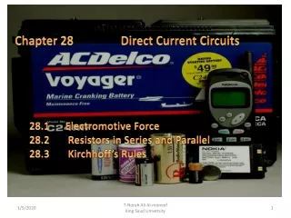
Chapter 28 Direct Current Circuits 28.1 Electromotive Force 28.2 Resistors in Series and Parallel 28.3 Kirchhoff’s Rules T-Norah Ali Al-moneef King Saud University
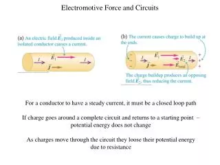
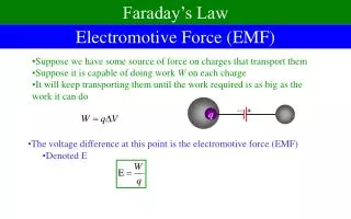
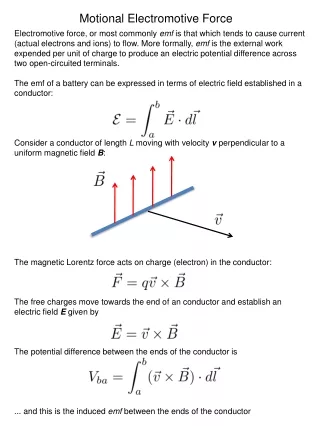
28.1 Electromotive Force A constant current can be maintained in a closed circuit through the use of a source of emf, (such as a battery or generator) that produces an electric field and thus may cause charges to move around a circuit. One can think of a source of emf as a “charge pump.” When an electric potential difference exists between two points, the source moves charges “uphill” from the lower potential to the higher. The emf describes the work done per unit charge, and hence the SI unit of emf is the volt. The emf of a battery 𝜺 is the maximum possible voltage that the battery can provide between its terminals. T-Norah Ali Al-moneef King Saud University
assume that the connecting wires have no resistance. • The positive terminal of the battery is at a higher potential than the negative terminal. If we neglect the internal resistance of the battery, the potential difference across it (called the terminal voltage) equals its emf. • However, because a real battery always has some internal resistance r, the terminal voltage is not equal to the emf for a battery in a circuit in which there is a current. A circuit consisting of a resistor connected to the terminals of a battery. T-Norah Ali Al-moneef King Saud University
As we pass from the negative terminal to the positive terminal, the potential increases by an amount ε. • As we move through the resistance r, the potential decreases by an amount Ir, where I is the current in the circuit. Figure 28.2 (a) Circuit diagram of a source of emf (in this case, a battery), of internal resistance r, connected to an external resistor of resistance R. • ε : is equivalent to the open-circuit voltage—that is, the terminal voltage when the current is zero. The emf is the voltage labeled on a battery,…. • the terminal voltage V must equal the potential difference across the external resistance R, often called the load resistance. T-Norah Ali Al-moneef King Saud University
the changes in electric potential as the circuit is traversed in the clockwise direction • The resistor represents a load on the battery because the battery must supply energy to operate the device. The potential difference across the load resistance is ΔV = IR Figure 28.2 (b) Graphical representation showing how the electric potential changes as the circuit in part (a) is traversed clockwise. • the total power output Iεof the battery is delivered to the external load resistance in the amount I 2R and to the internal resistance in the amount I 2r. T-Norah Ali Al-moneef King Saud University
Real Batteries I r = “internal resistance” of the battery A r I RL (external resistance, “load”) I B VB + - Ir = VA VA – VB = V = “terminal voltage” measured “Terminal voltage” ε - Ir = V T-Norah Ali Al-moneef King Saud University
Example 28.1 Terminal Voltage of a Battery A battery has an emf of 12V and an internal resistance of 0.05Ω. Its terminals are connected to a load resistance of 3Ω. Find: • The current in the circuit and the terminal voltage • The power dissipated in the load, the internal resistance, and the total power delivered by the battery T-Norah Ali Al-moneef King Saud University
T-Norah Ali Al-moneef King Saud University
Example * A battery has an emf of 15.0 V. The terminal voltage of the battery is 11.6 V when it is delivering 20.0 W of power to an external load resistor R. (a) What is the value of R? (b) What is the internal resistance of the battery? T-Norah Ali Al-moneef King Saud University
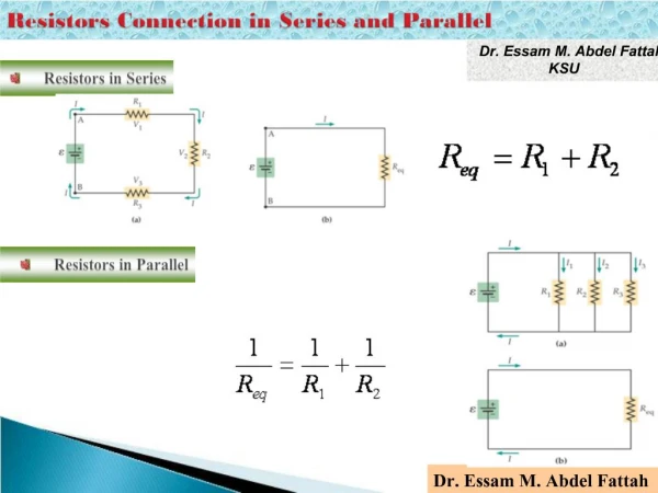
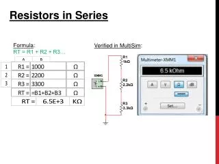
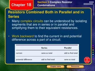
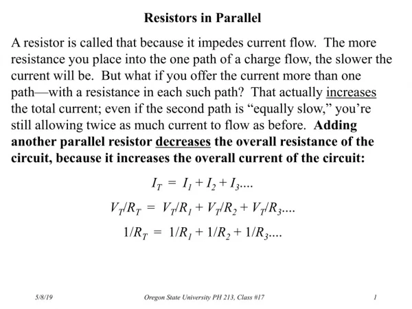
28.2 Resistors in Series and Parallel series connection When two or more resistors are connected together as are the light- bulbs, they are said to be in series. In a series connection, all the charges moving through one resistor must also pass through the second resistor. • for a series combination of two resistors, the currents are the same in both resistors because the amount of charge that passes through R1 must also pass through R2 This relationship indicates that the equivalent resistance of a series connection of resistors is always greater than any individual resistance. T-Norah Ali Al-moneef King Saud University
Find the equivalent resistance Re. What is the current I in the circuit? 2 W 1 W 3 W 12 V Example : Req = R1 + R2 + R3 Equivalent Req = 3 W + 2 W+ 1W= 6 W The current is found from Ohm’s law: V = IRe I = 2 A Current I = 2 A same in each R. V1 = IR1 ; V2 = IR2 ; V3 = IR3 V1 = (2 A)(1 W) = 2 V V1 + V2 + V3 = VTotal V1 = (2 A)(2 W) = 4 V 2 V + 4 V + 6 V = 12 V V1 = (2 A)(3 W) = 6 V T-Norah Ali Al-moneef King Saud University
Exmple 2 6 V 6 2. Find Itotal 1. Find Req 3. Find the V drops across each resistor. 1. Since the resistors are in series, simply add the three resistances to find Req: Req = 4 + 2 + 6 = 12 4 2. To find Itotal (the current through the battery), use V = IR:6 = 12 I.So, I = 6/12 = 0.5 A • Since the current throughout a series circuit is constant, use V = IR with each resistor individually to find the V drop across each. Listed clockwise from top: • V1= (0.5)(4) = 2 V • V2= (0.5)(2) = 1 V • V3= (0.5)(6) = 3 V Note the voltage drops sum to 6 V. T-Norah Ali Al-moneef King Saud University
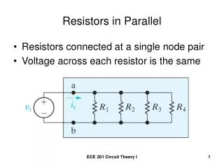
Now consider two resistors connected in parallel, When the current I reaches point a in Figure 28.5b, called a junction, it splits into two parts, with I1 going through R1 and I 2 going through R2 . A junction is any point in a circuit where a current can split when resistors are connected in parallel, the potential differences across the resistors is the same. T-Norah Ali Al-moneef King Saud University
3 Ω 2 Ω Req = 3 Ω + 2 Ω = 5 Ω Req = 6 Ω + 4 Ω = 10 Ω 6 Ω 4 Ω + - Calculate the total resistance in the circuit below Req= 3 .33 Ω 1/Req = 2/10 Ω+ 1/10 Ω = 3/10 Ω T-Norah Ali Al-moneef King Saud University
Parallel Example 1. Find Req 2. Find Itotal Itotal I2 3. Find the current through, and voltage drop across, each resistor. I1 15 V 1. 1/Req= 1/R1 + 1/R2 = 1/4 + 1/6 = 6/24 + 4/24 = 5/12 Req = 12/5 = 2.4 6 6 4 15 V 4 2. Itotal = V/Req = 15 / (12/5) = 75/12 = 6.25 A 3. The voltage drop across each resistor is the same in parallel. Each drop is 15 V. The current through the 4 resistoris (15 V)/(4 ) = 3.75 A. The current through the 6 resistor is (15 V)/(6 ) = 2.5 A. Check: T-Norah Ali Al-moneef King Saud University
Assume a 12-V emf is connected to the circuit as shown. Find the equivalent resistance Refor the three resistors below. What is the total current leaving the source of emf? VT R1 R2 R3 2 W 4 W 6 W 12 V Example Req = 1.09 𝜴 Vtotal = 12 V; V1 = V2 = V3 = 12 V IT = I1 + I2 + I3 Total current: IT = 11.0 A Ohm’s Law: T-Norah Ali Al-moneef King Saud University
Find the equivalent resistance for the circuit drawn below (assume VT = 12 V). Find the total current IT. 4 W VT 3 W 6 W 4 W 12 V 2 W 12 V 6 W Example Req = 4 W + 2 W = 6 W IT = 2.00A T-Norah Ali Al-moneef King Saud University
Find the currents and the voltages across each resistor. 4 W VT 3 W 6 W I4 = IT = 2 A V4 = (2 A)(4 W) = 8 V The remainder of the voltage: (12 V – 8 V = 4 V) drops across EACH of the parallel resistors. This can also be found from V3,6 = I3,6R3,6 = (2 A)(2 W) V3 = V6 = 4 V T-Norah Ali Al-moneef King Saud University
Find the currents and voltages across each resistor. 4 W VT 3 W 6 W V4 = 8 V V6 = V3 = 4 V I3 = 1.33 A I6 = 0.667 A I4= 2A T-Norah Ali Al-moneef King Saud University
(a) Find the equivalent resistance between points a and c. (b) What is the current in each resistor if a potential difference of 42V is maintained between a and c ? T-Norah Ali Al-moneef King Saud University
Three resistors are connected in parallel as shown in Figure 28.7. A potential difference of 18 V is maintained between points a and b. (a) Find the current in each resistor. (b) Calculate the power delivered to each resistor and the total power delivered to the combination of resistors. T-Norah Ali Al-moneef King Saud University
(c) Calculate the equivalent resistance of the circuit. Exercise :Use Req to calculate the total power delivered by the battery. Answer :200 W. T-Norah Ali Al-moneef King Saud University
If three equal resistors are in parallel, the total resistance is a. one third the value of one resistor b. the same as one resistor c. three times the value of one resistor d. there is not enough information to say T-Norah Ali Al-moneef King Saud University
- we can analyze simple circuits using the expression V IR and the rules for series and parallel combinations of resistors. Very often, however, it is not possible to reduce a circuit to a single loop. - The procedure for analyzing more complex circuits is greatly simplified if we use two principles called Kirchhoff’s rules: T-Norah Ali Al-moneef King Saud University
Kirchhoff’s first rule is a statement of conservation of electric charge. the charge passes through some circuit elements must equal the sum of the decreases in energy as it passes through other elements. The potential energy decreases whenever the charge moves through a potential drop IR across a resis-tor or whenever it moves in the reverse direction through a source of emf. The potential energy increases whenever the charge passes through a battery from the negative terminal to the positive terminal. T-Norah Ali Al-moneef King Saud University Fig 28-14, p.870
Kirchhoff’s second rule follows from the law of conservation of energy. Let us imagine moving a charge around the loop. When the charge returns to the starting point, the charge–circuit system must have the same energy as when the charge started from it. The sum of the increases in energy in some circuit elements must equal the sum of the decreases in energy in other elements. The potential energy decreases whenever the charge moves through a potential drop IR across a resistor or whenever it moves in the reverse direction through a source of emf. The potential energy increases when-ever the charge passes through a battery from the negative terminal to the positive terminal. T-Norah Ali Al-moneef King Saud University
Traveling around the loop from a to b • In a, the resistor is transversed in the direction of the current, the potential across the resistor is –IR • In b, the resistor is transversed in the direction opposite of the current, the potential across the resistor is +IR • In c, the source of emf is transversed in the direction of the emf (from – to +), the change in the electric potential is +ε • In d, the source of emf is transversed in the direction opposite of the emf (from + to -), the change in the electric potential is -ε T-Norah Ali Al-moneef King Saud University
(a) Find the current in the circuit. (Neglect the internal resistances of the batteries.) Traversing the circuit in the clockwise direction, starting at a, we see that a →b represents a potential change of +ε1 , b → c represents a potential change of - IR1 , c → d represents a potential change of -ε2 , and d → a represents a potential change of -IR2 . Applying Kirchhoff’s loop rule gives T-Norah Ali Al-moneef King Saud University
(b) What power is delivered to each resistor? What power is delivered by the 12-V battery? The 12-V battery delivers power Iε2. Half of this power is delivered to the two resistors, as we just calculated. The other half is delivered to the 6-V battery, which is being charged by the 12-V battery. T-Norah Ali Al-moneef King Saud University
Find the currents I1 , I2 , and I3 in the circuit We arbitrarily choose the directions of the currents as labeled in Figure Substituting Equation (1) into Equation (2) gives Dividing each term in Equation (3) by 2 and rearranging gives Subtracting Equation (5) from Equation (4) eliminates I 2 , giving The fact that I 2 and I 3 are both negative indicates only that the currents are opposite the direction we chose for them. However, the numerical values are correct. T-Norah Ali Al-moneef King Saud University
Exercise Find the potential difference between points b and c . Answer 2 V. T-Norah Ali Al-moneef King Saud University
h 30 I1 I3 40 1 2 = 45 V a a d d c b 20 I2 1 = 85 V 1 g e f Back to our circuit: we have 3 unknowns (I1, I2, and I3), so we will need 3 equations. We begin with the junctions. Junction a: I3 – I1 – I2 = 0 --eq. 1 Junction d: -I3 + I1 + I2 = 0 Junction d gave no new information, so we still need two more equations. T-Norah Ali Al-moneef King Saud University
h 30 I1 I3 40 1 2 = 45 V a d c b 20 I2 1 = 85 V 1 g e f Loop 1. Loop 2. Loop 3. There are three loops. Any two loops will produce independent equations. Using the third loop will provide no new information. T-Norah Ali Al-moneef King Saud University
Reminders: I + - V is - V is + loop loop 5 The “green” loop (a-h-d-c-b-a): (- 30 I1) + (+45) + (-1 I3) + (- 40 I3) = 0 - 30 I1 + 45 - 41 I3 = 0 --eq. 2 The “blue” loop (a-b-c-d-e-f-g): (+ 40 I3) + ( +1 I3) + (-45) + (+20 I2) + (+1 I2) + (-85) = 0 41 I3 -130 + 21 I2 = 0 --eq. 3 skip algebra Three equations, three unknowns; the rest is “algebra.” Make sure to use voltages in V and resistances in . Then currents will be in A. T-Norah Ali Al-moneef King Saud University
Collect our three equations: I3 – I1 – I2 = 0 - 30 I1 + 45 - 41 I3 = 0 41 I3 -130 + 21 I2 = 0 Rearrange to get variables in “right” order: – I1 – I2 + I3 = 0 - 30 I1 - 41 I3 + 45 = 0 21 I2 + 41 I3 -130 = 0 Use the middle equation to eliminate I1: I1 = (41 I3 – 45)/(-30) There are many valid sets of steps to solving a system of equations. Any that works is acceptable. T-Norah Ali Al-moneef King Saud University
Two equations left to solve: – (41 I3 – 45)/(-30) – I2 + I3 = 0 21 I2 + 41 I3 -130 = 0 Might as well work out the numbers: 1.37 I3 – 1.5 – I2 + I3 = 0 21 I2 + 41 I3 -130 = 0 – I2 + 2.37 I3 – 1.5 = 0 21 I2 + 41 I3 -130 = 0 Multiply the top equation by 21: – 21 I2 + 49.8 I3 – 31.5 = 0 21 I2 + 41 I3 -130 = 0 T-Norah Ali Al-moneef King Saud University
Add the two equations to eliminate I2: – 21 I2 + 49.8 I3 – 31.5 = 0 + ( 21 I2 + 41 I3 -130 = 0 ) 90.8 I3 – 161.5 = 0 Solve for I3: I3 = 161.5 / 90.8 I3 = 1.78 Go back to the “middle equation” two slides ago for I1: I1 = (41 I3 – 45)/(-30) I1 = - 1.37 I3 + 1.5 I1 = - (1.37) (1.78) + 1.5 I1 = - 0.94 T-Norah Ali Al-moneef King Saud University
Go back two slides to get an equation that gives I2: – I2 + 2.37 I3 – 1.5 = 0 I2 = 2.37 I3 – 1.5 I2 = (2.37) (1.78) – 1.5 I2 = 2.72 Summarize answers so your lazy prof doesn’t have to go searching for them and get irritated (don’t forget to show units in your answer): I1 = - 0.94 A I2 = 2.72 A I3 = 1.78 A Are these currents correct? How could you tell? We’d better check our results. T-Norah Ali Al-moneef King Saud University
I3 – I1 – I2 = 0 - 30 I1 + 45 - 41 I3 = 0 41 I3 -130 + 21 I2 = 0 I1 = - 0.94 A I2 = 2.72 A I3 = 1.78 A 1.78 – (-0.94) – 2.72 = 0 - 30 (-0.94) + 45 - 41 (1.78) = 0.22 ? 41 (1.78) -130 + 21 (2.72) = 0.10 ? Are the last two indication of a mistake or just roundoff error? Recalculating while retaining 2 more digits gives I1=0.933, I2=2.714, I3=1.7806, and the last two results are 0.01 or less roundoff was the culprit. T-Norah Ali Al-moneef King Saud University
What is the total resistance of this circuit? 1.) 66 ohms 2.) 60 ohms 3.) 54 ohms 4.) 25 ohms 5.) 15 ohms T-Norah Ali Al-moneef King Saud University
What is the current that flows in this circuit? 1.)10 amps 2.) 1 amp 3.) 0.1 amp 4.) 0.3 amp 5.) 0.03 amps T-Norah Ali Al-moneef King Saud University
B. . A What is the current that flows in this circuit at point B? 1.)288 amps 2.) 1.5 amp 3.) 0.1 amp 4.) 0.5 amp 5.) 0.03 amps What is the current that flows in this circuit at point A? 1.)288 amps 2.) 1.5 amp 3.) 0.1 amp 4.) 0.5 amp 5.) 0.03 amps T-Norah Ali Al-moneef King Saud University
EMF volts 1 2 3 For three resistors in parallel, choose the correct statement: A. The current and the voltage across all three are the same. B. The voltage drop and the power dissipated across all three are the same. C. Power delivered = sum of the power dissipated across all three resistors. D. The current through one resistor is the same as the current through the battery. T-Norah Ali Al-moneef King Saud University
How much current I runs through this circuit: A. 0.25 Amps B. 0.375 A C. 0.67 A D. 1.50 A E. 2.25 A 3 V 4 W 4 W T-Norah Ali Al-moneef King Saud University
10. The total power dissipated in a parallel circuit is equal to the a. power in the largest resistor b. power in the smallest resistor c. average of the power in all resistors d. sum of the power in all resistors T-Norah Ali Al-moneef King Saud University
Figure 28.18 (Example 28.10) A multiloop circuit. Kirchhoff’s loop rule can be applied to any closed loop, including the one containing the capacitor. T-Norah Ali Al-moneef King Saud University
T-Norah Ali Al-moneef King Saud University
T-Norah Ali Al-moneef King Saud University
Homework 1. Find Req 2. Find Req T-Norah Ali Al-moneef King Saud University Fig P28-6, p.885
3- Find Req , current in each resistor , voltage across each resistor 4- T-Norah Ali Al-moneef King Saud University Fig P28-15, p.886