Download
1 / 7
110 likes | 168 Vues
Learn how resistors impede current flow in parallel circuits, how to calculate total resistance, and simplify complex circuits. Includes examples and Kirchhoff's Rules explained in a study guide format.

E N D
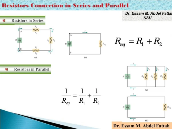
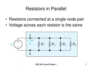
Resistors in Parallel A resistor is called that because it impedes current flow. The more resistance you place into the one path of a charge flow, the slower the current will be. But what if you offer the current more than one path—with a resistance in each such path? That actually increases the total current; even if the second path is “equally slow,” you’re still allowing twice as much current to flow as before. Adding another parallel resistor decreases the overall resistance of the circuit, because it increases the overall current of the circuit: IT = I1 + I2 + I3.... VT/RT = VT/R1 + VT/R2 + VT/R3.... 1/RT = 1/R1 + 1/R2 + 1/R3.... Oregon State University PH 213, Class #17
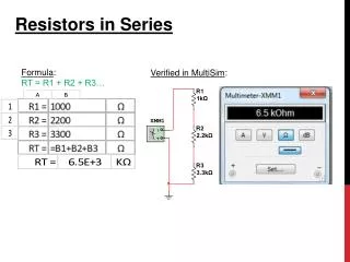
Example: Find the total resistance of a set of three resistors, connected in parallel: R1 = 5 W R2 = 10 W R3 = 10 W 1/RT = 1/R1 + 1/R2 + 1/R3 = 1/5 + 1/10 + 1/10 = 2/5 So RT = 1/(2/5) = 5/2 = 2.5 W Oregon State University PH 213, Class #17
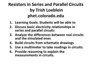
Simplifying Multiple-Resistor Circuits Sometimes, circuits can be modeled with simpler versions—arrangements that carry the same total current via fewer resistors. You can do this by using the rules for series and parallel resistors. Example: Find the total power dissipated in this circuit by modeling it as one equivalent resistance: A 15 V battery with a 1/4 internal resistance is connected to two parallel branches. In the first branch, there is just a 19 resistor. In the second branch there is a 5 resistor in series with two other parallel resistors, 2 and 4. 1. 30.0 W 2.45.0 W 3. 60.0 W 4. 75.0 W 5. None of the above. Oregon State University PH 213, Class #17
Example: Find the power dissipated by each of the resistors in the circuit from the previous slide (where we already know that RT = 5 W, IT = 3 A, and PT = 45 W). Assign these resistor names: R1 = 1/4 R2 = 19 R3 = 5 R4 = 2 R5 = 4 Then: I1= 3 A DV1= 3(1/4) = 0.75 V P1 = I12R1 = 32(1/4) = 2.25 W I2= DV2/R2 = [(15 – 0.75) – 0]/19 = 0.75 A P2 = I22R2 = 0.752(19) = 10.69 W I3= 3 – 0.75 = 2.25 A DV3= 2.25(5) = 11.25 V P3 = I32R3 = 2.252(5) = 25.31 W I4= DV4/R4 = [(15 – 0.75 – 11.25) – 0]/2 = 1.50 A P4 = I42R4 = 1.502(2) = 4.50 W I5= DV5/R5 = [(15 – 0.75 – 11.25) – 0]/4 = 0.75 A P5 = I52R5 = 0.752(4) = 2.25 W Notice: These all add up to 45 W. Oregon State University PH 213, Class #17
The circuit below has five identical light bulbs.Which statement is false? • Bulb 1 is the brightest. • Bulbs 2 and 3 are equally bright. • Bulbs 4 and 5 are equally bright. • Bulb 5 is twice as bright as bulb 2. • None of the above Oregon State University PH 213, Class #17
Kirchhoff’s Rules The two general tools for analyzing circuits are called Kirchhoff’s Rules, but they come directly from the fundamental principles of the conservation of energy and conservation of charge: 1.The Junction Rule (conservation of charge): The current flowing into any junction must equal the current flowing out of that junction. 2.The Loop Rule (conservation of energy): In any complete loop around a circuit, the sum of all voltage changes must be zero. These hold for both steady state and transient situations. Oregon State University PH 213, Class #17