Download
1 / 24
250 likes | 477 Vues
Compatibility of multivendor Dense Wavelength Division Multiplexing System. Master Thesis Jan Waldén, Helsinki Supervisor PhD Timo Korhonen. Table of contents. Optical characteristics Optical Signal to Noise Ratio Polarisation Mode Dispersion Chromatic dispersion

E N D
Compatibility of multivendorDenseWavelength Division Multiplexing System Master Thesis Jan Waldén, Helsinki Supervisor PhD Timo Korhonen
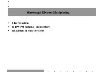
Table of contents • Opticalcharacteristics • OpticalSignal to NoiseRatio • PolarisationMode Dispersion • Chromatic dispersion • Optical Transport Network • ModulationMethods • ForwardErrorCorrection • Testsetup • Testresults • ITU-T specifications • Conclusions
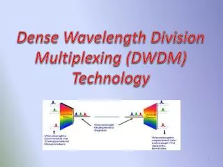
Opticalcharacteristics • Transport Multiple wavelengths in onefibre. • A DWDM system is today mostcommonlyimplemented in the C-band, that is between 1530nm and 1565nm. • For example 1552,52nm equals 193,1 THz. • Conversion from frequency to wavelengthf=c/. The speed of light in the fibre is approximately two thirds of the speed of light in vacuum.
Opticalcharacteristics • Channel spacingaccording to ITU-T G.694. • 100 GHz is approximately 0,8nm • 50 Ghz is approximately 0,4nm • 25 GHz is approximately 0,2nm • 12,5 GHz is approximately 0,1nm • Commonchannelsspacings in the backbonenetwork are the 100GHz and 50GHz spacing • With 50GHz spacing the number of channels in the C-band is between 72 to 88 channelsdepending on the mux/demuxtype.
OSNR • When the OSNR is toolow the BER starts to increase. • Forward ErrorCorrection (FEC) can be used to improve the BER • at low OSNR • - Whenplanning the DWDM network OSNR is the limitingfactor • Amplifying the signal alsoamplifies the noise • 3R regeneration (reamplification, reshaping, retiming) • Needed OSNR for modulation and linecodes
PMD • Twoorthogonal polarisation modes travel at different speed and causespulsebroadening. • The refractive index is not constant at any cross sectional area of the fibre • The polarisation modes willhave different refractiveindexes and propagate at different velocity
Chromaticdipersion • Broadening of the pulse • High frequenciestravels faster thanlowfrequencies • Difference in the refractive index ->differentvelocity • Intersymbol interference • Mitigation of chromatic dispersion • Dispersion compensationfibre • ChirpedfibreBragggrating • Electronic dispersion compensation
OTN Client signal OPU payload The ODU OH Added The OPU OH Added The OTU OH Added with the FEC Over head OCh The OCh OH Added OTU OPU ODU In every step the where an overhead is added the the former payload with the overhead becomes the new payload
End to endcircuit OMS 3R OTS OTS 3R Transponder MUX Switch OA OA MUX MUX Transponder OCh OTU/ODU Transponder MUX MUX OA OA MUX MUX Transponder 3R 3R
MUX/DEMUX Vendor D ATT 1 ATT 4 ATT 2 OA DCM DCM ATT 3 OA STM64
Vendor B and C opticallevels Site X Site Y VOA 0,04 dB Rx -10 dBm Site Z Rx -4 dBm OPOUT -1,7 dBm -18,6 dBm Tx-13,9 dBm OA OA md OA OA md Loop WSS GMD OA OA OA OA -4,4 dBm Out -9,2 dBm VOA 1,61 dBm 0 dBm -18,6 dBm VOA 1,6 dB System B System C
G.959 DWDM interoperability with post-andpre-amplifiers
G.698.1 Metro DWDM withoutamplifiers
Interoperability of DWDM capacity DWDM End Terminal VendorX DWDM ring Terminal VendorX DWDM end Terminal Vendor X DWDM End Terminal Vendor Y According to G.698.1 metro DWDM applicationshave a Standard OTU1 and OTU2 G.709 frame with FEC in order to enable Interoperability for Spans withoutlineamplifier OCh OCh G.698.1 OTU1 and OTU2 OTU1 and OTU2 ODU1 and ODU2
Conclusion • OSNR toleranceimproved with FEC. The FEC is implemented on everychannel. Compatibilityissue, the same FEC has to be used by the transponders in bothends. • Chromatic Dispersion DCF (compensates all channelseasier to use with foreignwavelengths) or eDCO (compensatesonechannel) and reducesattenuation on the linerestricts the use of foreignwavelengths. • Tolerances of Modulation methods , compatibilitydepends on whichmethod is chosen by the vendors.
ITU-T specifications • G.871 Framework for Optical Transport Network Recommendations coordination of the • G.872 Architecture of optical networks • G.650.2 Definitions and test methods for statistical and nonlinear related attributes of single mode fibre and cable • G.652 Characteristics of a single mode fibrecable • G.694.1Spectral grids for WDM applications: DWDM frequency grid • G.698.1 Multichannel DWDM applications with single-channel Optical interfaces • G.709: Interfaces for the Optical Transport Network (OTN) • G.798: Characteristics of Optical Transport Network hierarchy equipment functional blocks • G.957 Optical interfaces for equipment and systems relating to synchronous digital hierarchy • G.959 Optical transport network physical layer interfaces • G.975 Forward error correction for high bit-rate DWDM submarine systems