STATICALLY DETERMINED PLANE BAR STURCTURES ( BEAMS )
200 likes | 342 Vues
STATICALLY DETERMINED PLANE BAR STURCTURES ( BEAMS ). Superposition principle.

STATICALLY DETERMINED PLANE BAR STURCTURES ( BEAMS )
E N D
Presentation Transcript
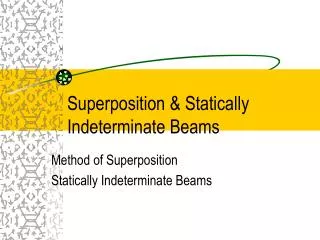
Superposition principle To determine cross-sectional forces we need to know all external loadings including reaction of different type of supports. This can be easily done if we assume solely for this purpose that the body is non-deformable – as we did in Theoretical Mechanics. Therefore, we deal with linear systems and we can exploit superposition principle. It says, in our case, that the effect of sum of different loadings is equal the sum of effects of individual loadings. This is a principal property of so called linear systems. As the result we will use linear algebra as already done considering the relation of M-Q-q. Quite often it is worthwhile to apply this principle when we have to deal with complicated loadings, and therefore it is strongly recommended in practical use. It is much easer to avoid mistakes when considering simple loadings and summing up their effects than to deal with very complex ones.
4 kN 2 kN 2 m 2 m 4 m K + RP RL Superposition principle An example of the use of superposition principle for determination of support reactions 1 kN/m Y 4 MNm 2 kN MK=0 +1·4·(2+2+4/2) +2·2 +4 = 0 32+8RP=0 +(2+2+4)·RP RP = - 4 Y=0 + RL - 2 - 1·4 – RP = 0 RL= 6 + RP RL= 6 – 4 = + 2
2 m 4 m 2 m 1 kN/m + + 4 kNm 2 kN K 4 kN 2 kN 1,5 kN 1 kN/m 1 kN Superposition principle Y Y=0 MK=0 = 2 kN RL= 2,0 RR = 4,0 RL1=[2·6]/8=1,5 RR1=0,5 + 0,5 kN 4 kNm RL2=-4/8= - 0,5 RP2=0,5 + 0,5 kN 0,5 kN RP3=3,0 RL3=[1·4 ·2]/8=1,0 3,0 kN
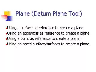
Beams Typical simple beams Pin-pointed (or simply supported) beam Cantilever beam Semi-cantilever beam
Q N N n n Q o o Beams Fundamental assumptions used for drawing diagrams of cross sectional forces 1. Diagram of bending moment will appear always on the side of a beam which is subjected to the tension caused by this bending moment. Therefore, no sign is necessary. 2. We will make use of q-Q-M dependence: 3 . Shear and normal forces will be always marked with their sign according to the following convention:
Q a b M M l Pb/l Pa/l Q Q N N n n Q Pab/l Pl/4 o o + P/2 - P/2 Typical beams P q0 M=cx+b Q=c q=d M=dx2/2+ex+f Q=dx+e + Pb/l - Pa/l P P/2 P/2 l/2 l/2
P P a a M M l l P P Q Q Pa + P - P q ql/2 ql/2 l/2 l/2 ql2/8 ql/2 + - ql/2 Typical beams q=d M=dx2/2+ex+f Q=dx+e
M/l M M M M/l Ma/l Q Q Q Mb/l - M/l M M M/l M/l M/l M/l M M - M/l M/l + M a b l
P l a M M M Q Q Q M M M/l M/l M M qa - - M/l M/l Typical beams P(1+a/l) Pa/l Pa P(1+a/l) + P [1+(a/l)]2[ql/2] [1-(a/l)2][ql/2] - Pa/l q l a qa2/2 l l a a + - (l/2)[1-(a/l)2]
P P·a P q·a2/2 M M M M N n q·a Q Q Q Q M qa o - M/l Cantilever beam P(1+a/l) Pa/l l a Pa P(1+a/l) + P - Pa/l q M [1+(a/l)]2[ql/2] M/l M/l l a l a qa2/2 + - (l/2)[1-(a/l)2]
Gerber’s beams The concept of multiple co-linear beams
Q0, N0M=0 Q0, N0M=0 Gerber’s beams
K Y = 0 Y MK = 0 X Gerber’s beams B A Formal definition: the set of aligned simple bars, hinged together and supported in the way which assures kinematical stability Number of unknown reactions:4 horizontal + 4 vertical Equilbrium equations X = 0 1 equation 4 unknown horizontal reactions Structure is statically indetermined with respect to horizontal reactions 2 equations 4 unknown vertictal reactions MA = 0 2 equations MB = 0
HYPER-STIFF HYPER-STIFF UNSTABLE UNSTABLE Gerber’s beams Number of unknown reactions to be found:1 horizontal reaction from 1 equilibrium equation (or we accept indeterminancy with respect to normal cross-sectional forces)(2 + n) remaining reactions (vertical reactions, moment reactions) from 2 equilibrium equations and n equations of vanishing bending moment in hinges Number of hinges is determined from the second of the above condition: structures appears to be kinemtaically unstable if there are too many hinges, and hyper-stiff – if there are too little hinges). However, the location of hinges – even if their number is correct one – cannot be arbitrary! WRONG! WRONG! GOOD!
M Gerber’s beams Partitioning of a Gerber’s beam into series of simple beams allows for better understanding of structure’s work!
Gerber’s beams SUPERPOSITION! + + + + + =
M Q + + + + Gerber’s beams SUPERPOSITION!