Download
1 / 4
70 likes | 273 Vues
Explore the thoughtful layout of an AX84 P1 amplifier with meticulous attention to parts placement and design for optimal performance. This guide showcases the strategic placement of components for a quiet, high-quality sound output.

E N D
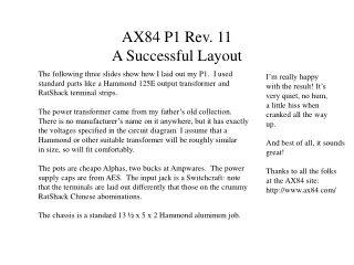
AX84 P1 Rev. 11A Successful Layout The following three slides show how I laid out my P1. I used standard parts like a Hammond 125E output transformer and RatShack terminal strips. The power transformer came from my father’s old collection. There is no manufacturer’s name on it anywhere, but it has exactly the voltages specified in the circuit diagram. I assume that a Hammond or other suitable transformer will be roughly similar in size, so will fit comfortably. The pots are cheapo Alphas, two bucks at Ampwares. The power supply caps are from AES. The input jack is a Switchcraft: note that the terminals are laid out differently that those on the crummy RatShack Chinese abominations. The chassis is a standard 13 ½ x 5 x 2 Hammond aluminum job. I’m really happy with the result! It’s very quiet, no hum, a little hiss when cranked all the way up. And best of all, it sounds great! Thanks to all the folks at the AX84 site: http://www.ax84.com/
AX84 P1 Rev. 11 Chassis Layout, Bottom View 7.5” 1.5” IEC Connector under Fuseholder Output Jack 12AX7 EL84 Holes used to mount terminal strips 1.25” Hole w/ grommet Power Transformer 2.0” 4.0” 2.5” 5.0” Hole w/ grommet Output Transformer Holes used to mount terminal strips 1.5” 1.5” 3.5” 5.5” Hole w/ grommet Input Jack Vol Bass Mid Treble Standby Power Pilot 1.0” 2.25” 0.625” 3.5” 1.25” 4.75” 2.0” 6.0” 13.5” This layout is for mounting “Bassman”-style in the back of a cabinet, or for “upside-down” mounting, with the tubes pointing down, front panel facing forward. For a “hi-fi” type layout (tubes pointing up), look at the drawing in a mirror. The transformers are on top of the chassis, their leads coming through grommeted holes. Adjust the locations of the power transformer and the output transformer to fit your particular iron.
47uF 47uF 47uF 47uF 47uF -|- -|- -|- 1 Meg AX84 P1 Rev. 11 Signal& PS Wiring, Bottom View B+ 10K/1W B+ 1K/1W 100K 100K 100K 220K/1W 1K/1W 68 K .022 820 130 1 uF 56K .015 470K .015 1.5K 1 uF 470K 470pF 270pF 100uF 100/1W 2.2M Approx. star ground point Input Jack Vol Bass Mid Treble To see this more clearly, set the magnification factor to 150%. There is really much more room than it appears. Most parts are smaller than shown… All of the grounds are brought together at a “star ground” just to the left of the output transformer primary. This point is isolated from the chassis. The only chassis connection is at the input jack. 220K/1W 10K/1W
AX84 P1 Rev. 11 AC Wiring, Bottom View 100 100 Approx. star ground point Input Jack Vol Bass Mid Treble SPST Pilot 110V To see this more clearly, set the magnification factor to 150%. There is really much more room than it appears. Most parts are smaller than shown… The fuse holder is mounted above or below the IEC connector. The pilot light is a cheapo RatShack job, 110V, with wire leads. 220K/1W