Download
1 / 21
210 likes | 421 Vues
Mechanical Measurement and Instrumentation MECN 4600. Professor: Dr. Omar E. Meza Castillo omeza@bayamon.inter.edu http://www.bc.inter.edu/facultad/omeza Department of Mechanical Engineering Inter American University of Puerto Rico Bayamon Campus. Tentative Lecture Schedule.

E N D
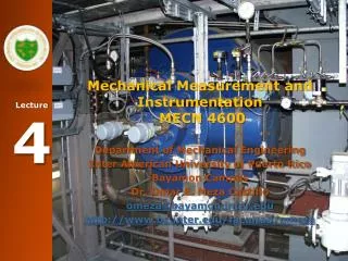
Mechanical Measurement and Instrumentation MECN 4600 Professor: Dr. Omar E. Meza Castillo omeza@bayamon.inter.edu http://www.bc.inter.edu/facultad/omeza Department of Mechanical Engineering Inter American University of Puerto Rico Bayamon Campus
Topic 10: Measurement of Fluid Flow Venturi Tube and Plate Orifice
Course Objectives • Measure the mass flow rate using two apparatus: the Venturi Tube and the Orifice Plate. • Establish the calibration curve of a rotameter using the gravimeter method as a comparison.
Theory • For steady , adiabatic flow of an incompressible fluid along a stream tube, as shown in figure, Bernoulli’s equation can be written in the form;
Theory • The head loss ΔH12 may be assumed to arise as a consequence of vortices in the stream. Because the flow is viscous a wall shear stress then exists and a pressure force must be applied to overcome it. The consequent increase in flow work appears as increased internal energy. Also, because the flow is viscous the velocity profile at any section is non-uniform. The kinetic energy per unit mass at any section is then greater than V2/2g and Bernoulli's equation incorrectly assesses this term.
Theory • The fluid mechanics entailed in all but the very simplest internal flow problems is too complex to permit the head loss to be obtained by other than experiential means. Since a contraction of stream boundaries can be shown (with incompressible fluids) to increase flow uniformity and a divergence correspondingly decreases it, is typically negligibly small between the ends of a contracting duct but is normally significant when the duct walls diverge.
Results and Calculations • Calculations of Discharge: The venturi meter, the orifice plate meter and the rotameter are all dependent upon Bernoulli's equation for their principal of operation. The following have been prepared from a typical set of results to show the form of calculations.
Results and Calculations Venturi Meter
Results and Calculations Venturi Meter Since ΔH12 is negligibly small between the ends of a contracting duct it, along with the Z terms, can be omitted from Equation (1) between stations (A) and (B).
Results and Calculations Orifice Meter
Results and Calculations Orifice Meter Between tappings (E) and (F) ∆H12 in Equation (1) is by no means negligible. Re-writing the equation with the appropriate symbols, i.e. the effect of the head loss is to make the difference in manometric height (hE- hF.) less than it would otherwise be. An alternative expression is
Results and Calculations where the coefficient of discharge K is given for the particular geometry of the orifice meter. For the apparatus provided K is 0.601. Reducing the expression in exactly the same way as for Venturi Meter, Since with the apparatus provided, the bore at (E) is 51mm and at (F) is 20mm.
Results and Calculations Rotameter
Results and Calculations Rotameter Observation of the recordings for the pressure drop across the rotameter (H)-(I) shows that this difference is large and virtually independent of discharge. Though there is a term which arises because of wall shear stresses and which is therefore velocity dependent, since the rotameter is of large bore this term is small. Most of the observed pressure difference is required to maintain the float in equilibrium and as the float is of constant weight, this pressure difference is independent of discharge. The cause of this pressure difference is the head loss associated with the high velocity of water around the float periphery. Since this head loss is constant then the peripheral velocity is constant. To maintain a constant velocity with varying discharge rate, the cross-sectional area through which this high velocity occurs must vary. This variation of cross-sectional area will arise as the float move up and down the tapered rotameter tube.
Results and Calculations Rf Rotameter Rt
Results and Calculations Rotameter
Results and Calculations Rotameter
Laboratory: Measure the mass flow • Table of Data • Setup the experiment • Measure the head in the Rotameter, Venturi Tube and Plate Orifice • Obtain the value of Flow in the Rotameter (Standard) • Calculate the Zero Shift and Sensitivity Shift