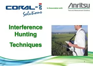
Anti-Interference and Jamming Techniques
Anti-Interference and Jamming Techniques. Agenda. Overview General Interference Testing Interference Signal Generators Embedded Interference Signal Generation CRPA Testing CRPA Overview Laboratory Testing with Embedded Interference Anechoic Chamber Testing


Anti-Interference and Jamming Techniques
E N D
Presentation Transcript
Anti-Interference and Jamming Techniques Proprietary & Confidential—Page 1
Agenda • Overview • General Interference Testing • Interference Signal Generators • Embedded Interference Signal Generation • CRPA Testing • CRPA Overview • Laboratory Testing with Embedded Interference • Anechoic Chamber Testing • Laboratory Testing with Phase Shift Matrix Proprietary & Confidential—Page 2
Interference Threats Like other RF communication, GPS and other GNSS signals are susceptible to interference Interference is of particular significance for GNSS/GPS, which has very low received power, well below the noise floor There are many sources of interference, both unintentional and intentional: AM and FM modulated signals from radio, mobile and other communication systems pulsed continuous wave (CW) or noise sources from a radar system CW or swept CW for a generic signal coming in and out of the GPS band Electromagnetic interference (EMI) from other equipment Jammers Proprietary & Confidential—Page 3
Interference Testing • Tests are conducted to determine how receivers and systems perform when subjected to different kinds of interference • There are benefits to using simulators for testing, instead of live field trials • Laboratory conditions • Controlled and repeatable testing • Avoid restrictions against jamming in public • The general techniques immediately following are suitable for testing traditional FRPA (Fixed Reception Pattern Antenna) systems • The specialized techniques following later are needed for testing CRPA (Controlled Reception Pattern Antenna) systems Proprietary & Confidential—Page 4
Interference Signal Generators • Spirent GSS7765 is used in combination with Spirent GPS/GNSS simulators • GSS7765 consists of • Up to 4 interference signal generators • Interference Combiner Unit (ICU) to combine GPS/GNSS RF • SimGEN controls the GPS/GNSS simulation with interference • Programmed interference source locations • Automatic and manual controls for interference power levels Proprietary & Confidential—Page 5
GSS7765 Interference Signals • GSS7765 signal generators offer the following types of interference signals • CW (coherent or non-coherent, wrt GNSS) – a generic signal • Swept CW – as above, with ability to move in and out of GNSS band • AM and FM – radio, mobile and other comms systems • Gaussian Noise – any source of spread-spectrum signal where encoding is unknown to receiver • Pulsed CW – radar, for example • Pulses noise Proprietary & Confidential—Page 6
GSS7765 Interference Combiner Unit • The GSS7765 ICU combines the GPS/GNSS and interference RF signals • An ICU is shown here configured for 2 RF outputs, and with 4 interference sources Interference Signal Generators Proprietary & Confidential—Page 7
Interference File • Add “Interference” to antenna • Access “Interference file” from Antenna Options • Allows time-ordered list of commands • Two interference modes = “Fixed” & “Modelled” • Four standard signal types = “CW”, “AM”, “FM” & “Pulse” • One advanced signal type = “Noise” (require higher spec signal generator model) Proprietary & Confidential—Page 8
Interference File Commands • Commands must be in chronological order • Each command specifies • One of four possible interference channels (a single STR4765 equates to one channel) • The signal type required and any signal specific parameter settings • Signal power defines “received” signal level • Fixed mode • Designates an interference source that ‘moves’ with vehicle to give a constant, ‘fixed’ power throughout scenario • Modelled mode • Designates a static interference source location, lat/long/hgt, (shown on ground track) • Signal power follows 1/r2 relationship and specified “power level” designates INITIAL power at scenario start Proprietary & Confidential—Page 9
Interactive Interference Control • Access by clicking “Interactive Interference” toolbar button • Enables quick-access to interference control • Manual control during scenario run for all four channels • No need to prepare timed-order commands; but • Can switch between file and interactive controls as necessary • Interactive window allows • Full “fixed” mode like control • View signal settings during “file” playback • “Modelled” mode control not supported Proprietary & Confidential—Page 10
Interference & Quick-Look Data • Use Quick-Look Data controls to access interference signal data • (see previous session on quick-look data) • “Interference” Tx type allows “Antenna” and “Signal” keyword sets only • “Ground Tx” Tx type allows “Antenna”, “Signal” and “Transmitter” only • Example shows • two “modelled” mode interference sources “Jam1” & “Jam2” • Plots of received power from each interferer • Vehicle moving away from Jam2 • Vehicle moving toward Jam1 Proprietary & Confidential—Page 11
Embedded Interference Signals • The 2 RF output configuration of Spirent GSS8000 supports internal (“embedded”) generation of in-band L1 and/or L2 interference signals combined with GPS • Up to (12 L1 + 12 L2) GPS + (12 L1 + 12 L2) Interference • Also available in alternate configuration,up to (16 L1 + 16 L2) GPS + (8 L1 + 8 L2) Interference • Coherent GPS and interference signals • Up to 61dB Interference-to-Signal (I/S) • SimGEN controls thesimulation of GPS andinterference • Programmed interference source locations Proprietary & Confidential—Page 12
GSS8000 Embedded Interference • The first bank of channels generates GPS • The second bank of channels generates interference • The high-power interference output is fed back and combined with GPS into coherent RF output High PowerOut 2 GSS8000 Bank #2 InterferenceL1 + L2 Bank #1 GPS L1 + L2 RF Out 1 Jammer In 1 SimGEN PC Ethernet Proprietary & Confidential—Page 13
Embedded Interference Signals • The GSS8000 offers the following types of interference signals • CW • BPSK • Using a PRN code derived from GPS L5 • 10.23 MHz BW • Other interference waveforms could be developed, as needed Proprietary & Confidential—Page 14
Embedded Interference “Ground Tx” • Add Ground Tx (GTx) signal type to antenna • Access GTx sources file to configure • 2 Main Sections GTx locations GTx signal characteristics Proprietary & Confidential—Page 15
GTx Location • Set the location of each GTx • Choose “Absolute” or “Relative” position mode • Absolute • Set Lat/Long/Hgt for each GTx; or • Use “Define Cells” to create a cellular layout defining cell centre • Relative • Set GTx distance from vehicle start CofG position; or • Use “Map editor” to simply drag-and-drop each GTx into position required from vehicle CofG Proprietary & Confidential—Page 16
GTx Signal Control • Select “Modelled” or “Fixed” power mode • Select “CW” or “PSK” signal type • “PSK Code” = PRN code derived from GPS L5 (10.23MHz BW with sin(x)/x waveform) • “Freq Offset” = offset from GPS L1 • “Fixed Power” = if “Fixed” has been in ‘General’ section • Modelled Power • Set transmitter launch power; or • Use “Rx power” to set vehicle antenna received power relative to distance from GTx • Off Times Proprietary & Confidential—Page 17
Embedded Interference Ground Track Tx = Interference source “x” location on ground track graphic Proprietary & Confidential—Page 18
CRPA Overview • Controlled Reception Pattern Antenna • Consists of a multi-element antenna and an antenna electronics (AE) unit for processing the signals from each element • Military applications • Some commercial • Null Generation • Reduces antenna gain in thedirection of interference • Beam Forming • Creates high gain beams in thedirection of satellites Antenna Electronics 7-element Antenna Proprietary & Confidential—Page 19
CRPA Gain Adjustment Jammer GPS (OK) ReceptionAntenna Gain N GPS (attenuated) Proprietary & Confidential—Page 20
CRPA Testing Challenges • CRPAs have multiple antenna elements • Testing requires providing suitable RF signals to each element • CRPAs determine the directions of interference signals by detecting timing and phase differences between the signals arriving at the different antenna elements • Testing requires proper timing and phase relationships between the signals provided to each element • The timing and phase of the interference signals must be coherent with the GPS signals • Timing and phase relationships must be maintained, even with dynamic vehicle motion Proprietary & Confidential—Page 21
CRPA Testing with Embedded Interference • Multiple Spirent GSS8000s simulators can be combined into a CRPA test system, with each GSS8000 generating the combined GPS and interference signals for one CRPA element • Coaxial cables are connected directly to theCRPA antenna electronics unit, bypassing the CRPA antenna RF Inputs Antenna Electronics (AE) Proprietary & Confidential—Page 22
GSS8000 CRPA Tester Configuration • A single SimGEN PC controls the entire system • Additional amplifiers can boost the I/S to higher levels • All capabilities of the GSS8000 are supported, including SA/AS and modernized signals • Interference signals are generated internally with GPS, and are kept coherent with GPS, even with vehicle dynamics • Each GSS8000 generates GPS (L1 + L2) and interference (L1 + L2) for one antenna element Proprietary & Confidential—Page 23
CRPA Testing in Anechoic Chamber • A Spirent GSS7790 simulator generates RF signals for individual satellites, which are transmitted through antennas positioned along the satellite lines of sight relative to the CRPA system • Scenarios typically last no more than 30 minutes, because the satellite locations are static • Independent interference sources can be placed in the chamber • The actual CRPA antenna is used in the testing • Vehicle motion typically is limited Proprietary & Confidential—Page 24
Generates separate L1 and L2 RF outputs for each GPS satellite Up to 12 L1 + 12 L2 channels One RF output per channel Supports SA/AS and modernized signals Provides increased power at each individual output for enhanced flexibility, and to compensate for transmission path losses GSS7790 Multi-output Simulator Proprietary & Confidential—Page 25
CRPA Testing with Phase-Shift Matrix • A GPS7790 simulator can also provide GPS signals for use with a phase-shift matrix or more complex DSP system • The DSP system combines the GPS and independently-generated interference signals, and makes the timing and phase adjustments needed for each antenna element Proprietary & Confidential—Page 26
Example of GSS7790 with DSP System • This is an example of a CRPA test solution consisting of a GSS7790 combined with a complex DSP system • The DSP system combines signals and introduces delays in the digital domain, and then upconverts the results back to L1 and L2 RF outputs • Coaxial cables connect the RF outputs directly to the CRPA antenna electronics unit, bypassing the CRPA antenna • Spirent collaborated with the company that built this system – Spirent provides GSS7790 simulators, but does not offer DSP systems such as this Proprietary & Confidential—Page 27