Real-time Extreme Space Weather Monitoring: The FOREWARN Detector and Simulation Techniques
This document outlines the FOREWARN Detector's capabilities and construction for monitoring extreme space weather conditions through real-time observations. Designed by Khalil Boudjemline for the ESW Workshop in October 2011 in Québec, Canada, it measures muon flux, angles, and energy cut-off. The report covers the detector's geometry, trigger systems, and operational principles, incorporating GEANT4 simulation for construction and data analysis. Insights into drift chamber mechanics, gas choices, and detector alignment are emphasized to enhance readiness against space weather events.

Real-time Extreme Space Weather Monitoring: The FOREWARN Detector and Simulation Techniques
E N D
Presentation Transcript
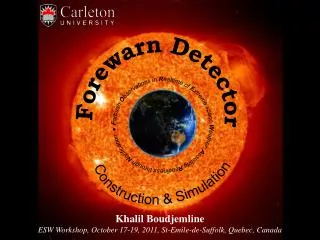
Forewarn Detector ForbushObservations in Realtime of Extreme space Weather: Assisting Readiness through Notification ● Construction & Simulation Khalil Boudjemline ESW Workshop, October 17-19, 2011, St-Emile-de-Suffolk, Quebec, Canada
Outline 2 Forewarn Detector Trigger System Drift Chamber GEANT4 Simulation Conclusion ESW Workshop, October 17-19, 2011, St-Emile-de-Sufolk, Quebec, Canada Khalil Boudjemline
1. FOREWARN Detector Goal 3 • Measure the muon flux. • Determine the muon angle. • Measure the muon energy cut-off. Ottawa, Ontario (Latitude 45º 19 N, Longitude 75º 40 W) acceptance acceptance Solar Altitude Angle a Zenith angle q Solar Azimuth Angle A Solar angles Sun Chart for Ottawa ESW Workshop, October 17-19, 2011, St-Emile-de-Sufolk, Quebec, Canada Khalil Boudjemline
1. FOREWARN Detector Geometry 4 • 10 plastic scintillators • 2 drift chambers • 2 x 10cm lead • DAQ & preamplifiers • NIM modules • Few gas cylinders 67º max stage 1 stage 2 stage 3 37º max sq = 2.5º sx,y = 3mm ESW Workshop, October 17-19, 2011, St-Emile-de-Sufolk, Quebec, Canada Khalil Boudjemline
1. FOREWARN Detector Construction 5 3 2 1 Coordinate system Steel plates First lead layer 6 5 4 Second lead layer Start to build the tower Tower construction completed 9 8 7 Detector alignment Gas system, scintillators Connections. ESW Workshop, October 17-19, 2011, St-Emile-de-Sufolk, Quebec, Canada Khalil Boudjemline
1. FOREWARN Detector Final Setup 6 Gas output Instrumentation Gas exhaust PMT + scintillator Drift chambers Lead Steel plates ESW Workshop, October 17-19, 2011, St-Emile-de-Sufolk, Quebec, Canada Khalil Boudjemline
2. Trigger system Scintillators & PMTs 7 • 10 plastic scintillators connected to Hamamatsu Photomultiplier Tubes. • 6 small (38-45, 60)cm, 4 large (57, 220)cm. Light guides PMT Small prototype Light collection system Scintillator + PMT Lower or upper Efficiency of the large scintillators decreases with the distance to the PMT. → slide one over the other lower upper ESW Workshop, October 17-19, 2011, St-Emile-de-Sufolk, Quebec, Canada Khalil Boudjemline
2. Trigger system Time Coincidence 8 • NIM modules used for the time coincidence. OR T1 T12 T2 Ti Triggers (from discriminator) 40ns 40ns OR T34 T3 T4 Trigger stages Si OR T5 T56 T6 Li Left events AND L2 DAQ S1 L1 OR T78 T7 T8 AND DAQ DAQ S2 OR T910 T9 T10 AND S3 DAQ ESW Workshop, October 17-19, 2011, St-Emile-de-Sufolk, Quebec, Canada Khalil Boudjemline
3. Drift Chamber Detector candidate 9 • Inspiredfrom OPAL*experimentat CERN with few changes: • a) zig-zagshape cathode instead of diamondshape cathode. • b) aroundtwice the drift length. • c) shorter anode wire. • d) thinner anode wire (higherresistance). • 2D position measurement. • a) X: drift time. • b) Z: zig-zag. • - 5 outputs per chamber (anode x 1, cathode x 4). • - relatively cheap. • - covers large area (0.4m x 1.2m). *J. Allison et Al.. NIM A310 (1991) 527-534. ESW Workshop, October 17-19, 2011, St-Emile-de-Sufolk, Quebec, Canada Khalil Boudjemline
3. Drift Chamber Active area Geometry 10 46 cm Active area of the Drift Chamber. ¼ W: 10cm • Drift distance: 0.57m • Anode wirelength: 46cm • Anode-Cathode distance: 0.75cm • Anode wire: 25um diameter, tungsten. • Zigzag cathode: 40cm wavelength, 1.3cm width. • Drift electrodestrips: 1cm width, 0.1cm gap. upper anode wire lower W: 40cm Top view of the zig-zag cathodes. • High Voltage: • a) Cathode: 3000V-6000V. • b) Anode-Cathode: 1500V-2000V. • c) Strips: from 0V to ~Cathode V. ESW Workshop, October 17-19, 2011, St-Emile-de-Sufolk, Quebec, Canada Khalil Boudjemline
3. Drift Chamber Construction 11 • Copper electrodes machined on a printed circuit board made of FR4 fiber glass with a thickness of 3.1 mm. • FR4 is laminated with 2.5 cm of expanded Styrofoam and an outer layer of FR4 with a continuous copper shield. • Gap between both cathodes is set by two G10 manifolds. Exploded view. zigzag & wire electrodes manifold zigzag 1MW HV board Interior view. HV board Zigzag pattern. ESW Workshop, October 17-19, 2011, St-Emile-de-Sufolk, Quebec, Canada Khalil Boudjemline
3. Drift Chamber Potential Map 12 • Successive Over-Relaxation Method. • Iterative method. • Divide the area into cells (0.01cm step). • Uses known HV values (electrodes, wire…). neighbour cells main cell 2D Potential Map. ESW Workshop, October 17-19, 2011, St-Emile-de-Sufolk, Quebec, Canada Khalil Boudjemline
3. Drift Chamber Principle of Operation 13 • Gas ionization. • Electron drift + diffussion. • Electron amplification. • Induction of the signal on the cathodes. Electron drift. ESW Workshop, October 17-19, 2011, St-Emile-de-Sufolk, Quebec, Canada Khalil Boudjemline
3. Drift Chamber Gas Choice 14 Idealgas • Low transverse and longitudinal diffusions. • Low drift velocity but high enough to avoid event pile-ups. • Stability of the velocity versus drift distance. Best gas • Ar/C2H6(10%) used by Jade and OPAL. • Flammable. Othergases • Ar/CH4(10%): fast gas. • Ar/CO2 (15%): very slow gas. • Combine both? Properties of different gas mixtures. ESW Workshop, October 17-19, 2011, St-Emile-de-Sufolk, Quebec, Canada Khalil Boudjemline
3. Drift Chamber DAQ & Electronics 15 Data Acquisition System • National Instruments*. • Built in PC/windows. • - PXI chassis with a fast backplane readout by Labview. • - 16 channel input. • - 10MHz F-ADC cards (100ns samples). Data Acquisition System Preamplifiers Cathodes and wire: Cremat CR-112* charge amplifiersrise & decay times (7ns, 50us). Preamplifier Board *www.ni.com/pxi *www.cremat.com ESW Workshop, October 17-19, 2011, St-Emile-de-Sufolk, Quebec, Canada Khalil Boudjemline
3. Drift Chamber Position Determination 16 Induced charge Top cathode pulses Bottom cathode pulses 1. Amplitude of each zig and zag pulses. 2. zig-zag of each cathode. 3. Plots each difference vs the other (diamond). 4. Convert the diamond to a circle using MC. 5. Y Position. Top vs bottom. Cathode vs Y. ESW Workshop, October 17-19, 2011, St-Emile-de-Sufolk, Quebec, Canada Khalil Boudjemline
4. GEANT4 Simulation Geometry & Materials 17 X Thickness material formula density (cm) (g/cm3) Scintillators 0.3 / 1.5 polystyrene C8H8 1.04 Drift 7.1 see below see below see below Chambers Lead 10 lead Pb 11.35 Iron 2.5 iron Fe 7.87 Materials used for the simulation Y Thickness material number density (g/cm3) Active 1.5cm argon gas 1 1.78 x 10⁻³ Electrodes 60mm copper 4 8.96 or Shielding G10 skin 3.1mm SiO2 4 1.91 Styrofoam 2.5cm polystyrene 2 0.03 Drift chamber materials used for the simulation ESW Workshop, October 17-19, 2011, St-Emile-de-Sufolk, Quebec, Canada Khalil Boudjemline
4. GEANT4 Simulation Particles & Physics 18 • Particles generated using CRY software*. • Particles generated: electrons, protons and muons. Other particles (kaons & pions) have low flux. • Latitude: 45º. • Altitude: 0m. • Angular distribution: cos2q. Multiple Ionization Bremsstrahlung Pair Scattering Production Protons Electrons Muons Muon energy loss in lead Physics used for the simulation *http://nuclear.llnl.gov/simulation/main.html ESW Workshop, October 17-19, 2011, St-Emile-de-Sufolk, Quebec, Canada Khalil Boudjemline
4. GEANT4 Simulation Particle Tracks 19 electrons • Electrons: most are stopped in the first lead layer • Protons: some can reach the last trigger. • Muons: most can make it to the last trigger. • PS: gammas are not shown. protons muons ESW Workshop, October 17-19, 2011, St-Emile-de-Sufolk, Quebec, Canada Khalil Boudjemline
4. GEANT4 Simulation Results generated 20 • Generated = detected + lost (geometrical acceptance & absorbed ) • electrons: no events in stage 2. • protons: very few survived. • muons: using stage 1 as reference: the rate is reduced by 4% and 14% in stages 2 and 3 respectively. • momentum cut-off: 0.2GeV/c and 0.4GeV/c in stages 2 and 3 respectively. • expected trigger rate / stage 1: • stage 2: ~85% • stage 3: ~76% generated stage 1 detected stage 2 stage 3 ESW Workshop, October 17-19, 2011, St-Emile-de-Sufolk, Quebec, Canada Khalil Boudjemline
5. Conclusion 21 Detector • A small scale muon tower has been built with available components. • DAQ needs to be modified to include different trigger stages. • Data will start to be taken within the next 2 weeks. • Analysis code exists but needs minor modifications. • Inefficiency of the large scintillators has to be corrected using event hit position in the drift chambers. • No temperature, pressure corrections. Simulation • Expected event rate in different stages: (85%,76%) / main trigger (stage 1) • Basic tool used for particle generation (CRY). • → need more robust generator. • No energy loss in the roof. ESW Workshop, October 17-19, 2011, St-Emile-de-Sufolk, Quebec, Canada Khalil Boudjemline