ASAR INSTRUMENT CALIBRATION
230 likes | 405 Vues
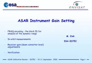
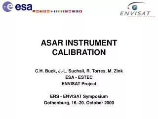
ASAR INSTRUMENT CALIBRATION. C.H. Buck, J.-L. Suchail, R. Torres, M. Zink ESA - ESTEC ENVISAT Project ERS - ENVISAT Symposium Gothenburg, 16.-20. October 2000. ASAR antenna is an active phased array, 320 T/R modules

ASAR INSTRUMENT CALIBRATION
E N D
Presentation Transcript
ASAR INSTRUMENT CALIBRATION C.H. Buck, J.-L. Suchail, R. Torres, M. Zink ESA - ESTEC ENVISAT Project ERS - ENVISAT Symposium Gothenburg, 16.-20. October 2000
ASAR antenna is an active phased array, 320 T/R modules Each T/R module has two transmit chains (H/V) and one receive chain, each chain is independently programmable in amplitude and phase => 32 transmit/receive beams alternating polarization mode, ScanSAR operation Digital chirp generator Block adaptive quantiser (BAQ) Differences between ASAR and ERS
Internal Monitoring/Calibration In-Orbit Check-Out Antenna Pattern Characterization Absolute Gain Calibration Calibrated Products Temperature Profiles PF-ASAR processor normalization antenna pattern gain drift ACF Calibration Pulses Antenna Model Transponder Measurements Rain Forest MS22 Preflight Data External Characterization ASAR Calibration Steps
ASAR is equipped with an automatic temperature compensation scheme to compensate for phase/gain drifts at T/R module level Direct monitoring of any residual gain drifts for later correction It is desirable to have continuous measurements even during data acquisition Use of special calibration signals (cal pulses) and additional hardware (cal network) Internal Calibration: Objectives
P3 P2 Tx Aux P1A P1 P1 P1 Cal BFN Cal Rx Aux Internal Calibration Pulse Diagram T/R Module (1 of 32x10) Radiating Row Signal BFN Tx Main Rx Main
Row by row measurement in a pre-determined sequence campaign: Monitoring of gain drifts Elevation beam pattern calculation Replica reconstruction Corrections applied in the ground processor update rate 5 - 35 s (mode dependent) Does not include the passive part of the antenna and the calibration network Internal Calibration
Radiometric performance requires accurate knowledge of the two-way antenna beam (0.1dB) Transmit and receive antenna patterns have been measured on ground for all eight beams and both polarizations In-flight, the patterns will be re-determined using several techniques: Module Stepping (T/R module characteristics only) External Characterization (transmit only) Rain Forest or other suitable distributed targets (two-way, mainlobe only) Antenna Pattern Characterization
Antenna Pattern: Preflight Characterization • All antenna beams have been characterised as part of the on-ground test campaign: • Main beam measured to an accuracy of 0.1 dB (to be checked with Rain Forest overpasses) • Full sidelobe structure compared with required template (to be checked by processing module stepping and external characterisation data) • On-ground characterisation data to be used by the Ground Processor initially • Capability to re-synthesise the pattern validated during FM test campaign
Antenna Pattern Characterization: Module Stepping • A dedicated Module Stepping Mode has been implemented to gather all data from all T/R Modules automatically: • Sampling performed in less than 1 second for all 320 Modules using calibration pulse P1 • Data to be downloaded and processed on ground • Data to be compared wrt reference Database from on-ground tests • Results of the analysis will provide information of: • T/R Module gain and phase drift and temperature behaviour • T/R Failures • Outcome used to: • Implement corrections by updating T/R Module coefficients • Re-synthesis of antenna beams if required
P1 Ground Receiver Antenna Pattern: External Characterization Tx Aux Radiating Row Signal BFN Tx Main Rx Main Cal BFN Cal Rx Aux
Antenna Pattern: External Characterization • A series of cw-pulses - sent by each row in turn - is simultaneously sensed by the antenna calibration loop and recorded on ground by the receiver embedded in the calibration transponder • Per row subtract amplitude/phase recorded on board from ground receiver measurements => characteristics of the passive part of the antenna minus calibration network • Antenna pointing error • Measurements will be repeated every 6 months
Antenna Pattern Characterization : Rain Forest • Stable and isotropic target with relatively high backscatter • Uncorrected image over the rain forest is averaged in the azimuth direction to produce the two-way mainlobe pattern • Suitability of other distribut-ed targets at different latitude is under investigation
The ASAR Gain Calibration uses the same technique as the ERS AMI-SAR, that is: The overall Absolute gain Calibration Factor (ACF) will be given by a single number per beam per polarisation (14 ACFs for Image Mode) Any user interested in the absolute level of the backscatter from a target (sigma 0) will make use of the ACF Gain Calibration: Objectives
Receive Detect Delay Transmit Amplify Gain Calibration: Techniques • The power in the IRF is integrated and the associated background power is measured in order to determine the ACF • A comparison with on ground measurements of the end-to-end system gain can then be made • Narrow swath modes: ERS methodology • ScanSAR modes: use of narrow swath calibration + dedicated calibration processing (support studies on calibration processing)
Gain Calibration: Targets • 3 fixed and 1 mobile ASAR precision transponders in the Netherlands: calibration mode, external characterization mode, receiver mode, decoupling of background contribution via frequency offset for GM calibration • one experimental transponder at ESTEC with option for pulse repetition, delay and coding • 4 RADARSAT transponders, 31 MHz frequency offset but • 100 MHz bandwidth, latitude range 45 - 74deg, • cross-calibration at 5.3 GHz successfully performed, • need to be characterized at 5.331 GHz
ASAR calibration plan is the logical progression from the experience gained with ERS Active phased array antenna requires a comprehensive internal monitoring network Antenna pattern characterization includes preflight data, measurements in special operating modes and rain forest acquisitions Absolute gain calibration is based on high precision ASAR transponders deployed in the Netherlands RADARSAT transponders will support verification of round-orbit calibration performance Image, Wave and Wide Swath modes calibrated within six months Conclusions
Beam Gain Beam Radiation Pattern Antenna Model Antenna Gain Test Results Transponder Calibration Beam Coefficients Module Stepping Internal Cal. Azimuth Pattern Antenna B/F Near-field data Rain Forest Elevation Pattern External Characterisation Embedded Row Test Results Antenna B/F Test Results
P3 P2 Tx Aux P1A P1 P1 Cal BFN Cal Rx Aux Internal Calibration Pulse Diagram T/R Module (1 of 32x10) Radiating Row Signal BFN Tx Main Rx Main
Impulse Response Function from transponder Spatial resolution defined as half-width of response Side-lobe levels Point-target ambiguity levels Radiometric Accuracy Radiometric Stability Localization Accuracy Noise Equivalent Sigma Nought Delimit the minimum sigma nought which can be measured Determined from the apparent backscatter obtained over still water such as a lake in an image In-Flight Evaluation of Performance Parameters