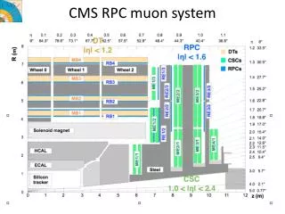
CMS LV Power System
CMS LV Power System. CMS LV Power System Peter Sharp 7 April 2003. CMS LV Power System. Motor Generator Sets ( 400 Hz 400V ). AC-DC Converters 400 V to 48V or 7V. Distribution System. A. B. C. D. CMS LV Power System. 400 Hz 400 Volts. 7v DC. AC - DC Converters.

CMS LV Power System
E N D
Presentation Transcript
CMS LV Power System CMS LV Power System Peter Sharp 7 April 2003 Peter Sharp CERN
CMS LV Power System Motor Generator Sets ( 400 Hz 400V ) AC-DC Converters 400 V to 48V or 7V Distribution System A B C D Peter Sharp CERN
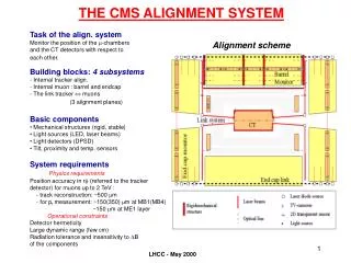
CMS LV Power System 400 Hz 400 Volts 7v DC AC - DC Converters LV Regs 'LVDB' Detector EMU HCAL Sense Wires 400 Hz 400 Volts 48v DC Commercial LV Power Supply AC - DC Converters Detector ~ 20 m Tracker ECAL (0.25) MB Cables Peter Sharp CERN
CMS LV Power System Proposed System Design -1 • Hard Wired Sensors – Continuous monitor (Temperature…) • If Detector ‘Safe’ switch on Control System(Low Power Dissipation) • Control System(Tracker and ECAL use Tracker System) • DCU provides comprehensive sensing of Detectors • If Detector ‘Safe’ prepare to switch on Low Voltage System • ‘Set-Up’ LV Regulators on Front End Electronics (ECAL) • Sequentially bring on Low Voltage Power Systems Peter Sharp CERN
CMS LV Power System Proposed System Design – 2 Sense Wires ~ 4V Commercial LV Power Supply Crate LV Regs on Detector AC - DC Converter 2.5V 48V DC ~ 4V ~ 20 m Power Cables Peter Sharp CERN
CMS LV Power System Proposed System Design – 3 Control of each PSU from DCS 8 or 10 Double Width Modules each contain 2 PSUs 6U Crate 48 Volts DC from AC - DC Converter ~ 3.5 KW Peter Sharp CERN
CMS LV Power System Proposed System Design – 4 Standard CMS Rack 6 * 6U Crates Each Crate - 16 or 20 PSUs Each Crate supplied from 1 AC-DC Converter Each Rack - 96 or 120 PSUs Each Rack supplied from 6 AC-DC Converters Peter Sharp CERN
CMS LV Power System Proposed Schedule • Agree Sub-Detector Requirements in May 2003 (Electronics Week) • Define Responsibilities of CERN and Fermi Lab in May 2003 • Outline Costs of System (for planning) in June 2003 • Complete Prototype AC-DC Converter Tests in September 03 • Sub-Detector Prototypes for System Tests in December 2003 • Review System and Integration Plans in December 2003 • Final Prototypes for tests with the Magnet in January 2005 Peter Sharp CERN
CMS LV Power System Proposed Decision Schedule • Agree to Fund theDesign of the CMS LV SystemToday • Agree Specifications of AC-DC Converters May 03 • Agree ‘Planning’ Costing of System June 03 • Agree System Design and Integration Plans Dec 03 • Agree Final Design of AC-DC Converters March 04 • Agree to Procure 2 MGSs Jan 04 • Install Power Distribution System March 05 Peter Sharp CERN