Download
1 / 54
550 likes | 724 Vues
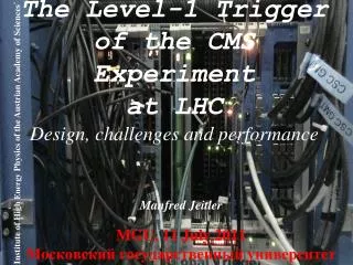
The Level-1 Trigger of the CMS Experiment at LHC Design, challenges and performance. Institute of High Energy Physics of the Austrian Academy of Sciences `. Manfred Jeitler MGU, 11 July 2011 Московский государственный университет. The Large Hadron Collider.

E N D
The Level-1 Trigger of the CMS Experimentat LHCDesign, challenges and performance Institute of High Energy Physics of the Austrian Academy of Sciences` Manfred Jeitler MGU, 11 July 2011 Московский государственный университет
LHC p-p CollisionsOperations 2010-2011 • 2010: √s = 7 TeV • Peak Instantaneous Luminosity:> 2×1032 cm-2s-1 • 2011: √s = 7 TeV • Peak Instantaneous Luminosity:> 1.25 ×1033 cm-2s-1 • And increasing! • Current Maximum of ~1400 bunches/beam in LHC • Possible to gain another factor of 4 2808
first particle physics experiments needed no trigger • were looking for most frequent events • people observed all events and then saw which of them occurred at which frequency what is a trigger?
what is a trigger? • later physicists started to look for rare events • “frequent” events were known already • searching “good” events among thousands of “background” events was partly done by auxiliary staff • “scanning girls” for bubble chamber photographs
Получше — в горшочек, похуже — в зобочек!
+30 MinBias Higgs ->4m
due to the extremely small cross sections of processes now under investigation it is impossible to check all events “by hand” • ~ 1013 background events to one signal event • it would not even be possible to record all data in computer memories • we need a fast, automated decision (“trigger”) if an event is to be recorded or not X-section
detectors yielding electrical output signals allow to select events to be recorded by electronic devices • thresholds (discriminators) • logical combinations (AND, OR, NOT) • delays • available in commercial “modules” • connections by cables (“LEMO” cables)
1 x 400 x • because of the enormous amounts of data at major modern experiments electronic processing by such individual modules is impractical • too big • too expensive • too error-prone • too long signal propagation times • use custom-made highly integrated electronic components (“chips”) ~ 10 logical operations / module ~ 40000 logical operations in one chip
example: trigger logic of the L1-trigger of the CMS experiment
When do we trigger ? • „bunch” structure of the LHC collider • „bunches” of particles • 40 MHz • a bunch arrives every 25 ns • bunches are spaced at 7.5 meters from each other • bunch spacing of 125 ns for heavy-ion operation • at nominal luminosity of the LHC collider (1034 cm-2 s-1) one expects about 20 proton-proton interactions for each collision of two bunches for ATLAS and CMS • only a small fraction of these “bunch crossings” contains at least one collision event which is potentially interesting for searching for “new physics” • in this case all information for this bunch crossing is recorded for subsequent data analysis and background suppression
trigger:first level high level ATLAS, CMS 40 MHz 100 kHz 200 Hz LHCb 40 MHz 1 MHz 2 kHz ALICE 10 kHz 1 kHz 100 Hz Event size (bytes)
read write How do we trigger ? • use as much information about the event as possible • allows for the best separation of signal and background • ideal case: “complete analysis” using all the data supplied by the detector • problem: at a rate of 40 MHz it is impossible to read out all detector data • (at sensible cost) • have to take preliminary decision based on part of the event data only • be quick • in case of positive trigger decision all detector data must still be available • the data are stored temporarily in a “pipeline” in the detector electronics • “short term memory” of the detector • “ring buffer” • in hardware, can only afford a few μs • how to reconcile these contradictory requirements ?
40 MHz 100 kHz 300 Hz to tape multi-level trigger • first stage takes preliminary decision based on part of the data • rate is already strongly reduced at this stage • ~1 GHz of events (= 40 MHz bunch crossings) ~100 kHz • only for these bunch crossings are all the detector data read out of the pipelines • still it would not be possible (with reasonable effort and cost) to write all these data to tape for subsequent analysis and permanent storage • the second stage can use all detector data and perform a “complete analysis” of events • further reduction of rate: ~100 kHz ~100 Hz • only the events thus selected (twice filtered) are permanently recorded
How does the trigger actually select events ? • the first trigger stage has to process a limited amount of data within a very short time • relatively simple algorithms • special electronic components • ASICs (Application Specific Integrated Circuits) • FPGAs (Field Programmable Gate Arrays) • something in between “hardware” and “software”: “firmware” • written in programming language (“VHDL”) and compiled • fast (uses always same number of clock cycles) • can be modified at any time when using FPGAs • the second stage (“High-Level Trigger”) has to use complex algorithms • not time-critical any more (all detector data have already been retrieved) • uses a “computer farm” (large number of PCs) • programmed in high-level language (C++)
How does the trigger actually select events ? • the first trigger stage has to process a limited amount of data within a very short time • relatively simple algorithms • special electronic components • ASICs (Application Specific Integrated Circuits) • FPGAs (Field Programmable Gate Arrays) • something in between “hardware” and “software”: “firmware” • written in programming language (“VHDL”) and compiled • fast (uses always same number of clock cycles) • can be modified at any time when using FPGAs • the second stage (“High-Level Trigger”) has to use complex algorithms • not time-critical any more (all detector data have already been retrieved) • uses a “computer farm” (large number of PCs) • programmed in high-level language (C++)
signals used by the first-level trigger • muons • tracks • several types of detectors (different requirements for barrel and endcaps): • in ATLAS: • RPC (Resistive Plate Chambers): barrel • TGC (“Thin Gap Chambers”): endcaps • not in trigger: MDT (“Monitored Drift Tubes”) • in CMS: • DT (Drift Tubes): barrel • CSC (Cathode Strip Chambers): endcaps • RPC (Resistive Plate Chambers): barrel + endcaps • calorimeters • clusters • electrons, jets, transverse energy, missing transverse energy • electromagnetic calorimeter • hadron calorimeter • only in high-level trigger: tracker detectors • silicon strip and pixel detectors, in ATLAS also straw tubes • cannot be read out quickly enough
how to find muon tracks in the CMS solenoidal field? (Drift Tubes)
how to find muon tracks in the CMS solenoidal field? (Resistive Plate Chambers) RPC Comparator Pattern matching barrel: 3 layers/4 or 4/6endcaps: 3/3
Muon Trigger • Muon Trigger • 3 muon detectors to |h|<2.4 • Drift Tubes • Track Segment ID and Track Finder • Cathode Strip Chambers • Track Segment ID and Track Finder • Resistive Plate Chambers • Pattern Matching • 4 candidates per subsystem to Global Muon Trigger • Global Muon Trigger sorts, removes duplicates, 4 top candidates to Global Trigger • Track building at 40 MHz
Global Muon Trigger • match & merge • barrel:DT-RPC • endcap:CSC-RPC • cancel duplicates • overlap region:DT-CSC • sort by momentum and quality
calorimeter system Hadronic calorimeter (HCAL) Electromagnetic (ECAL) HF Hadron Forward Calorimeter
Photon and electron trigger objects L1 e/gam HLT e/gam • L2 Step • Spatial matching of ECAL clusters with e/γ candidates at L1 • Superclusters are formed • ET cut applied • Calorimetric (ECAL+HCAL) isolation L3 Photons • Tight track isolation L3 Electrons • Electron track reconstruction • Spatial matching of ECAL cluster and pixel track • Loose track isolation in a “hollow” cone
e/g and Jet Algorithms 4x4 Tower sums from RCT to GCT Jet or t ET • 12x12 trig. tower ET sliding in 4x4 steps w/central 4x4 ET > others t: isolated narrow energy deposits • Energy spread outside t veto pattern sets veto • Jet t if all 9 4x4 region t vetoes off • GCT uses Tower sums used for ET,MET jets for HT, MHT • Electron (Hit Tower + Max) • 2-tower ET + Hit tower H/E • Hit tower 2x5-crystal strips >90% of ET in 5x5 (Fine Grain) • Isolated Electron (3x3 Tower) • Quiet neighbors: all towers pass Fine Grain & H/E • One “L” of 5 EM ET < Thr.
Global Trigger Receives Trigger Objects: • 4 forward and 4 central jets, 4 t-jets, 4 isolated and 4 non-isolated e/g, total ET, missing ET, HT and position information from GCT • 4 m with position, sign, and quality information from GMT 128 different conditions (thresholds, topological cuts) can be combined to make 128 physics triggers Forwards Level-1 Accept Trigger, Timing and Control (TTC) system for read-out of the detector front-end electronics
Global Trigger and Trigger Control System 40 MHz pipeline FINAL DECISION LOGIC • Every bunch crossing for which a potential Level-1 accept is inhibited is counted as “dead”. • needed to calculate recorded integrated luminosity GLOBAL TRIGGER LOGIC 1. Logic OR 2. Prescale 3. Rate Counters 128xalgos calo & muonobjects CMS regionaltriggers GCTGMT 64xtechnical technical trigger signals(beam monitoring systems etc.) TRIGGER CONTROL SYSTEM rand calib physics random calib deadtime counters L1A candidate backpressure, trigger rules GLOBAL TRIGGER Level-1 Accept (via TTC system to detector)
L1 Trigger Custom Hardware CSCTF (Florida) RCT (Wisconsin) DTTF (Vienna) • Hundreds of boards • Thousands of: • ASICs • FPGAs • Copper Cables • Optical Fibers • (Wo)man hours RPC PaC (Warsaw) GCT (Imperial) Global Muon Trigger & Global Trigger (Vienna)
The CMS Level-1 Trigger Calorimeter Trigger Muon Trigger DAQ • Only calorimeter and muon systems participate in CMS L1 ||<3 0.9<||<2.4 ||<1.2 ||<3 0<||<5 RPC hits CSC hits DT hits ECAL Trigger Primitives HCAL/HF Trigger Primitives Link system Segment finder Segment finder RegionalCalorimeterTrigger Track finder Pattern Comparator Track finder 40 MHz pipeline 4+4 m 4 m 4 m MIP+ISO bits GlobalCalorimeterTrigger Global Muon Trigger e, J, ET, HT, ETmiss 4 m Global Trigger L1A Status CMS experiment TTC system TTS system 32 partitions Detector Frontend
ATLAS+CMS:what’s the difference ? • similar task • similar conditions • similar technology
ATLAS+CMS:what’s the difference ? • similar task • similar conditions • similar technology
ATLAS+CMS:what is common ? • same physics objectives • same input rate • 40 MHz bunch crossing frequency • similar rate after Level-1 trigger • 50 .. 100 kHz • similar final event rate • 100 .. 200 Hz to tape • similar allowed latency • pipeline length • within this time, Level-1 trigger decision must be taken and detectors must be read out • ~ 3 μs • 2.5 μs for ATLAS, 3.2 μs for CMS
ATLAS+CMS:what is different ? • different magnetic field • toroidal field in ATLAS (plus central solenoid) • get track momentum from η (pseudorapidity) • solenoidal field only in CMS • get track momentum from φ (azimuth) • number of trigger stages • two stages (“Level-1” and “High-Level Trigger”) in CMS • ATLAS has intermediate stage between the two: “Level-2” • Level-2 receives “Regions of Interest (RoI)” information from Level-1 • takes a closer look at these regions • reduces rate to 3.5 kHz • allows to reduce data traffic
ATLAS+CMS:principle of the first-level trigger • data are stored in “pipelines” for a few microseconds • e.g. in CMS: 3.2 s = 128 clock cycles at 40 MHz • question of cost • decision must never take longer! (must be synchronous!) • no iterative algorithms • decision based on “look-up tables” • all possible cases are provided for • OR, AND, NOT can also be represented in this way
principle of event selection: ATLAS vs. CMS • ATLAS: • Level-1 trigger delivers numbers of candidate objects • muon tracks, electron candidates, jets over appropriate threshold • no topological information used (no angular correlation between different objects) • Level-2 trigger carries out detailed analysis for “Regions of Interest” • using complete detector information for these regions • High-Level trigger analyzes complete detector data for the whole detector CMS: • no “cuts” at individual low-level trigger systems • only look for muons, electrons, jets, choose the “best” of these candidate objects and forward to Level-1 Global trigger • so, all possible kinds of events may be combined • selection is only made by “Level-1 Global Trigger” • trigger information from all muon detectors and calorimeter systems available: completely flexible • High-Level trigger analyzes complete detector data for the whole detector
First Collisions • Tuesday March 30, 2010 • 12:58 • L~1027cm-2s-1 • ~ 60 Hz Collision Rate • Time to optimize the trigger synchronization!
Minimum Bias trigger detectors • HF – Hadron Forward Calorimeter • BSC – Beam Scintillator Counters (hit and coincidence rate, MIP detection eff >96%) • BPTX – Beam Pick-up Timing for the eXperiments monitors (precise info about bunch structure and timing of the incoming beam, res. 0.2 ns)
2010 Commissioning: Synchronizing the Trigger • Collision products take longer to get to outer part of detector • e.g. to reach CSC takes longer than ECAL • Take into account many different cable lengths • Even within a sub-detector • First runs with only a Minimum-Bias Trigger • Take data with a number of delays • Find the best alignment between subsystem (CSC shown) and Minimum-Bias Trigger • Repeated for each Trigger subsystem • Cross-checks available in DQM
2010 Commissioning: Synchronizing the Trigger • LHC is design to deliver one bunch crossing (BX) every 25 ns • Trigger has to provide a correct BX assignment • Optimization of the trigger synchronization allows for an overall efficiency increase Example: L1 RPC trigger synchronization is in a very good shape RPC Hits TRIGGERS BX=0 : 99.999% no pre-triggers
2010 Operational Challenge: Rates • Final month of 2010 p-p running, max inst. lumi increased by > O(4)! • No longer relying on Minimum Bias but a full menu of physics object triggers • L1 works with the HLT to maintain a sustainable HLT stored data rate • Up to 65 kHz in, ~400 Hz out • New L1 & HLT configurations and menus: • Higher thresh. L1 Triggers for HLT seeds • Prescaling at L1 and HLT to reduce rates • Several prescale “sets” to allow as much data to tape as possible • Lumi decreases -> change set of prescales, keep rate about the same • Possible to predict output rates with MC • Must take into account other factors • Cosmic backgrounds, pile-up effects, detector effects, etc.
2010 Trigger Efficiencies DT trigger performance • Threshold efficiency – probability that for reconstructed muon with momentum PT, track finder assigns momentum greater or equal to the threshold value CSC trigger performance Eta region |η|< 1.1 DTTF PT > 10 GeV/c from J/Psi“Turn-on” expected to reach >90% efficiency at the nominal cut Eta region 1.2 <|η|<2.1
2011: Operations: Controlling the Rates LHC has been steadily increasing instantaneous luminosity delivered to the experiments in 2011 • Well beyond what was delivered in 2010 • How do we best control rates while keeping as much physics as possible? Just a few examples of what the L1 Trigger can do: • e/g triggers • Energy corrections to improve resolution • ECAL Spike Killing • Isolation and H/E for e/g candidates • Jet triggers • Improve the resolution with jet energy corrections • Muon triggers • Improve ghost busting and pattern recognition • Continue to develop the L1-HLT menus with prescale sets • Must anticipate physics groups’ needs as conditions change
2011: Operations: Avoiding pre-triggers • Problem: • Triggers are pre-firing at about ~5% of the time • Forward hadron calorimeter • Can we avoid this source of inefficiency? • CMS BPTX_AND Trigger • AND of two precision electrostatic beam pick-ups • Provides colliding bunch structure in CMS for every fill • Copy, reduce delay by one bunch-crossing unit (25 ns) and shorten to ~20ns • Use it as veto on pre-triggers • But it vetoes the slow particle (HSCP) trigger (BX+1) when the bunch spacing is 50 ns! • How to fix this? (Next Slide) before after
2011 Operations: Trigger on HSCPs HSCP In-time muon Chamber hits Chamber hits extended hits Extended hits • Heavy Stable Charged Particles (HSCPs) take as much as 2 BX the detector • Look for late signal in muontriggers • But preBPTX veto during 50 ns bunch spacing vetoes these! • RPC Trigger can extend detector signal to 2 BX • Reduce RPC delay into GMT by 1 BX • preBPTX will veto early in-time muons • In-time muons still captured with collision BX • HSCPs aligned with collision BX • Create special HLT path to keep slow particles (the BXid will be +1 wrt to Tracker, for example). • HSCPs Triggering! layer 6 layer 6 layer 5 layer 5 layer 4 layer 4 layer 3 layer 3 layer 2 layer 2 BX BX layer 1 layer 1 Muon candidate Muon candidate BPTX BPTX
Halfway through 2011 Middle of 2011 p-p run: • 323 pb-1 data taken • Maximum sustained L1 rate of ~65 kHZ • 912b – 874 colliding at CMS, 50ns spacing • XX pb-1 recorded in a single fill