Download
1 / 21
210 likes | 415 Vues
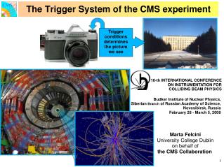
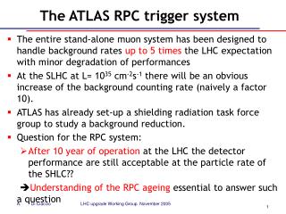
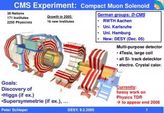
The RPC based muon trigger of the CMS Experiment. XI Workshop on Resistive Plate Chambers and Related Detectors, 5-10 Feb 2012, Laboratori Nazionali di Frascati dell'INFN, Frascati (Italy). CMS detector. The Trigger and D A ta Acquisition system at CMS. Level 1 Trigger

E N D
The RPC based muon trigger of the CMS Experiment XI Workshop on Resistive Plate Chambers and Related Detectors, 5-10 Feb 2012, Laboratori Nazionali di Frascati dell'INFN, Frascati (Italy)
CMS detector Karol Buńkowski, UW
The Trigger and DAtaAcquisition system at CMS Level 1 Trigger • Dedicated electronics (ASICs, FPGAs) @ 40 MHz, only logic functions • Analyses every event (bunch crossing, BX) • pipeline processing; latency 3.2 s, including ~2 s for data transmission between the detector and counting room, dead time free operation Output ≤100 kHz Detector Coarse data Readout buffers 128 events= 3.2 s keepreject DAQ: readouts the data for the selected events, the events are fragmented Event Builder - switching network. Gathers the data from one event into one HLT computer High Level Trigger (HLT) • Computer Farm: 1008 nodes, 9216 cores, 16 TB memory runs the software events selection algorithms • A few hundreds of Hz recorded on the magnetic tapes Karol Buńkowski, UW RPC2012, 5-10 February 2012
Level1 trigger system Calorimeter Trigger Muon Trigger DAQ RPC hits CSC hits DT hits ECAL Trigger Primitives HCAL Trigger Primitives Trigger subsystems: identify, measure and sort the trigger objects Link system Segment finder Segment finder RegionalCalorimeterTrigger Track finder Pattern Comparator Track finder 40 MHz pipeline 4+4 m 4 m 4 m MIP+ISO bits GlobalCalorimeterTrigger Global Muon Trigger Global Triggerapply cuts: single or multi-objects, topological correlations 4 m e/, J, ET, HT, ETmiss Global Trigger Status L1A (trigger) TTC system TTS system ` 32 partitions Detectors Frontend Karol Buńkowski, UW
Link Board Link Board Link Board Synchronization Unit & LMUX FEB FEB FEB FEB FEB FEB RPC PAC muon trigger Detector Counting room Control & diagnostic LVDS cables Ghost Buster & Sorter Trigger Board GB & Sorter SYNCH. & LDMUX PAC Optic Links 90 m @ 1.6 GHz 1104fibers PAC 1232Link Boards in96Boxes, Steered byControl Boards To theGlobal Muon Trigger PAC Data Concentrator Card RMB To Data Acquisition 84Trigger Boards in12Trigger Crates Data transmission @ 320 MHz Resistive Plate Chambers Up to 6 layers of detectors. 480 chambers in barrel, 504inendcaps * Numbers of elements for the staged version of the system Karol Buńkowski, UW
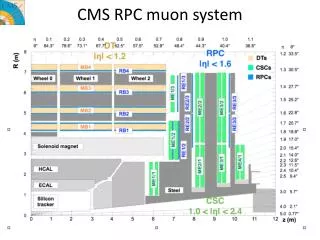
Geometry of the RPC detector and PAC trigger segmentation 6 concentric layers of chambers in the barrel region, and 3 disc layers in each endcap(currently to || < 1.6, the endcap detector is staged, the 4thendcap station will be added in 2013/2014) the detector is segmented in the eta plane into the trigger towers (~0.1-0.2 eta unit each) A tower comprise from 3 to 6 chamber layers in phi plane: 1152 strips in each layer one strip= 0.3125˚ Karol Buńkowski, UW
3/4 Trigger Algorithm: Pattern Comparator (PAC) The chamber signals (fired strips) are compared with the predefined set of patterns. Each pattern has assigned the pTand sign (depending on the track banding by the magnetic filed). Muon candidate is recognized if the hits fit to the pattern and are in the same clock period (BX) The candidate is generated even though not all planes have hits. The minimum required number of fired planes is 3 (out of 3, 4, 5 or 6 planes available – depending on a tower). In this way the trigger efficiency is not suffering from the limited geometrical acceptance and inefficiency of the chambers. The number of fired planes defines the candidate quality. The quality is used for the candidates sorting and “ghost busting” (cancelation of duplicated candidates). RPC layers strips A pattern is a set of AND gates connected to selected strips Karol Buńkowski, UW
Implementation of the PAC algorithm in the FPGAs The trigger algorithm is implemented in the FPGA devices -AlteraStratix 2, 300 chips are needed to cover full detector. Each PAC comprises max 576 chamber strips and contains 3 000 – 14 000 patterns (most of them low pT). The patterns are built-in the firmware logic. The patterns are generated based on the simulated muon track. Advanced algorithms are used to create the patters from the simulated chamber hits, assign the pT, and then select optimal set of patterns. The goal is to achieve best possible trigger efficiency and purity with a patterns set that can be fit into the PAC FPGAs. Since each PAC contains different patterns, for each chip separate compilation is needed. The software framework for patterns generation and firmware compilation on the computer cluster was created. One iteration takes ~24 hours. As the PAC algorithm is implemented in the reprogrammable FPGAs, it can be easy changed, e.g. to correct bugs, improve performance, or implement new features. Karol Buńkowski, UW
Synchronization of the trigger system (1) • The time of muon flight from the interaction point to the different chambers varies from 14 to 42 ns - more than 1 BX • The time of signal propagation from the chambers to the Link Boards varies from 33 to 107 ns (due to differences in the cables lengths) 14m = 42ns 4.2m = 14ns The chamber hits must be in the coincidence (in the same BX, i.e. 25 ns clock period) on the PAC input to produce the muon candidate the system synchronization is crucial for its performance Karol Buńkowski, UW
Synchronization of the trigger system (2) • The chamber hits are synchronized to the 40 MHz LHC clock in the Link Boards. The hits are “quantized” to the full BX (i.e. the timing is measured with the 25 ns precision) with used of the “synchronization window”. Its position can be adjusts with 0.1 ns accuracy. • Then the hits are aligned between the Link Bards by applying full BX delays. • The goal is to have all hits of all muons fromgiven event within 25 ns on all LBs. Synchronization window Synchronized signals LB1 delay 25ns propagationin cables Time offlight LB2 LB3 collision time • The initial position of the synchronization window winOpeniand data delaydidatawas calculated based on: • muon hits timing tihits which is a sum of the muon time of flight (know from the simulations) and signal propagation time in the cables, • known length of the fibers transmitting the clock (clock phase difference iTTC): • winOpeni = (tihits+ iTTC+ offset) % 25 ns • didata = a – int[(tihits + offset)/25ns] + bi - (1*) + ciwin+ (2SM) • Then the synchronization was corrected based on the collected collision data Karol Buńkowski, UW RPC2012, 5-10 February 2012
Calculation of the timing correction from hits BX distribution After the initial synchronization in most of the LBs the chamber hits were concentrated in ONE or TWO neighboring BXs: -1, 0, 1 Muon hits timing from simulations [ns] Hits distribution Cumulative distribution Assuming that the mean hits BX (from data) corresponds to the cumulative distribution function of the simulated timing of the hits, the timing correction can be calculated: From the data we know only the distribution of the hits in the BXes (w.r.t. the correct BX of the event). From this the value of the timing correction must be obtained. We have not measured the hits timing distribution from the collisions because it would required time consuming scanning. We utilized the hits timing distribution obtained from the simulations Timing correction #hits time window BX= -1 BX=0 BX=1 winOpen Karol Buńkowski, CERN, UW,
Synchronization of the trigger system - results • Since the start of the collisions in the April 2010 the synchronization was corrected 7 times. Distribution of chamber hits BX w.r.t. the event BX • Distribution of the hits mean timing and spread (rms) for individual Link Boards • Data selection!!!!!!!!!!!!!!!!! • In ??? of the 99.9??? % of hits is in the correct BX • Bad timing on a few LBs due to problems in chambers or signal cables • 99.98% of hits associated to the muon tracks are in the correct BX=0 Karol Buńkowski, UW
Trigger on HSCPs • Some supersymetry and models foresee Heavy Stable Charged Particles (HSCPs), e.g. stop, gluino, stau. They mass could range from ??? To ??? GeV, thus if produced at LHC they velocity would be ~0.2 – 0.9c. • In the CMS they will look like “slow muons”: the hits in the muon chambers (all or outermost) can be up to 1 BX later than the hits of the muons • they will not produced the muon trigger at all (hits not in coincidence in one BX) or • the trigger will be 1 BX to late the tracker hits will not be recorded (pixel detector stores only the hits from one BX/event). Karol Buńkowski, UW
Trigger on HSCPs PAC modification • In the PAC trigger we found a way to trigger on the HSCPs: • In the PACs the detector signal are extend to 2 BX and • On the GMT input the PAC candidates delay is reduced by 1 BX (w.r.t. the DT and CSC candidates) • the hits of the “late particle” generate the trigger in the proper BX! • for in-time muons candidates in 2 BX appear - the first candidate is too early, but he second is in the proper BX. • The first candidate is masked on the GT by the BPTX veto – signal synchronous to collision, but advanced 1 BX (used for all trigger to eliminate the pretriggering). late particle normal muon Chamber hits (PAC input) Chamber hits (PAC input) extended hits (in the PAC) extended hits (in the PAC) layer 6 layer 6 layer5 layer5 layer4 layer4 layer 3 layer3 layer2 layer 2 layer1 layer1 BX BX Muon candidate Muon candidate L1A L1A Masked by BPTX veto Guino800 GeV MonteCarlo Significant increase of the efficiency to trigger on lower momentum, slower moving HSCPs e.g. for gluino800 GeVfrom 24 to 32% Karol Buńkowski, CERN, UW,
Timing of the RPC PAC candidates results • 99.9??% of PAC candidates are in the correct BX=0 • BX of the RPC candidates w.r.t. the L1 trigger BX • Data selection!!!!!!!!!!!!!!!!! • The candidates corresponding to the muons from the collisions are duplicated in the BXs -1 and 0 • To early or to late candidates (~10-4) are mostly from the cosmic muons Karol Buńkowski, UW
Efficiency of the RPC detector and PAC trigger vs. The efficiency of RPC PAC trigger for identifying muons is a convolution of: • εacceptance– geometrical acceptance of the RPC detector (probability that muon crosses at least 3 chambers), • εchambers– chambers intrinsic efficiency, • εpatterns– patterns efficiency i.e. probability that the chamber hits of a “triggerable” muon fit to any pattern; “triggerable” muon – hits in at least 3 RPC layers inside the eta-phi cone covered by one PAC unit and in the same BX εtriggerable muon =εacceptanceεchambers • Detector acceptance • Triggerable muons • RPC PAC trigger eff. • Data selection and method !!!!!!!!!!!!!!!!! Karol Buńkowski, UW
RPC PAC efficiency- turn on curves • From tag and probe??? Karol Buńkowski, UW
RPC chambers monitoring via the PAC trigger hardware • In the Link Boards firmware the multichannel counters allowing to measure the signal rate for each strip individually are implemented: • All hits are counted: no bias from trigger (unlike in the DAQ data), big statistic, • The signals for all strips are counted, even those masked, • The data are stored for the offline analysis: neutron background, chamber noise noisy strips masking, Front-end thresholds tuning (see talk by ?????). • The basic plots (rate v.s. time for each chamber, average and maximal rate per strip) are produced in the real time by the software controlling the hardware – the chambers performance can be evaluated online, the problems (noisy strips, dead chambers) can be noticed promptly. Hits rate [Hz] Time [s] strips Karol Buńkowski, UW
2011 performance summary • Only a few minor hardware failures, promptly repaired. Beside that 100% of the trigger hardware operational and working correctly. • CMS down time (dead time?) due to the RPC PAC trigger during 2011 collisions only !!!% • Excellent synchronization of the system: 99.98% of muon chamber hits in the correct BX 99.99??% of the PAC candidates in the correct BX. • The only trigger subsystem capable to trigger on HSCP. • Average RPC PAC trigger efficiency 80???% . Continuous work on the patterns optimization, according the CMS requirements (efficiency – rate tradeoff) Karol Buńkowski, UW
backup Karol Buńkowski, UW