Dynamic CAMERA STABILIZATION SYSTEM
The Dynamic Camera Stabilization System, developed in collaboration with UAARG, is designed to enhance image processing capabilities of UAVs. This innovative system utilizes real-time data from sensors like GPS and IMU to stabilize camera platforms irrespective of aircraft movements. The goal is to maintain a fixed camera angle while tracking targets via their GPS coordinates. By leveraging an FPGA, it efficiently controls servo motors to ensure stability and precision in capturing images, even in challenging conditions, paving the way for advanced aerial imaging applications.

Dynamic CAMERA STABILIZATION SYSTEM
E N D
Presentation Transcript
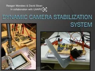
ReeganWorobec & David Sloan In collaboration with UAARG Dynamic CAMERA STABILIZATION SYSTEM
WHAT IS IT? • An additional system intended to enhance the image processing capabilities of UAARGs UAV • A dynamic stability controller that updates its position in real time based on aircraft pitch and roll • Has the potential to track ground targets given their GPS coordinates
WHAT DOES IT DO? • Stabilizes a camera platform relative to ground independent of aircraft pitch and roll • Gathers sensor data from an onboard GPS and IMU (Inertial Measurement Unit) and stabilizes a camera platform by means of a pair of servo motors
OUR GOAL • Develop a system utilizing an FPGA • Keep platform stabilized • Read GPS data, send positional instructions to servo motors to adjust platform • GPS point tracking • Set camera angle at fixed location as opposed to relative ground plane
HOW DOES IT DO THIS? • The IMU takes measurements at a rate of 50Hz and calculates required servo positions • This information is then forwarded to the PWM controller to update the servo motor positions • It constantly polls for these updates, sending speed calibration data from the GPS to the IMU, and adjusts camera angle
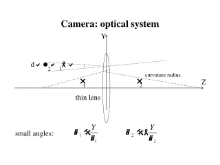
HOW DOES IT DO THIS? (con’t) • Essential Matrix math • Normalize input vectors (frame orientation, and gimble orientation) • Project onto the frame servo’s rotational plane • Calculate first servo rotation • Transform frame orientation with new servo position • Project onto the second servo’s rotational plane • Calculate second servo rotation and update servo positions • GPS parsing* • Reads in NMEA sentences and parses for relevant information *Function completed in a desktop environment but not implemented in demo project
THE FPGA • The initial design utilized an FPGA as a reconfigurable microcontroller • Communicates with Inertial Measurement Unit (IMU), GPS, Flight Computer, and two servo motors • Sends information to servos via PWM controllers
INTERRUPT CONTROLLER OUT <= IN1 or IN2 or IN3 or IN4
GPS INVOLVEMENT • GPS information is fed through a UART connection as a continuous stream • We have parsing routines written to extract vital information we need for the microcontroller • Fix (Latitude/Longitude) converted to radians • Altitude [m] • Speed [m/s] • Speed bearing (direction of travel) • NMEA sentence: • $GPGGA,123519,4807.038,N,01131.000,E,1,08,0.9,545.4,M,46.9,M,,*47
OBSTACLES • Difficult development environment to interface our components • Unfamiliar environment to create custom hardware • Numerous operating issues with some of our components • Two IMU chips became unusable • one DOA, and a second spontaneously shorted • FPGA breakout board came with pins un-soldered