Download
1 / 42
420 likes | 440 Vues
Explore the significant hardware upgrades and improvements to the KLOE detector with the KLOE2 project, including new read-out systems, gamma-gamma tagger, Inner Tracker, and more. Learn about the enhanced functionalities and planned physics experiments.

E N D
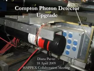
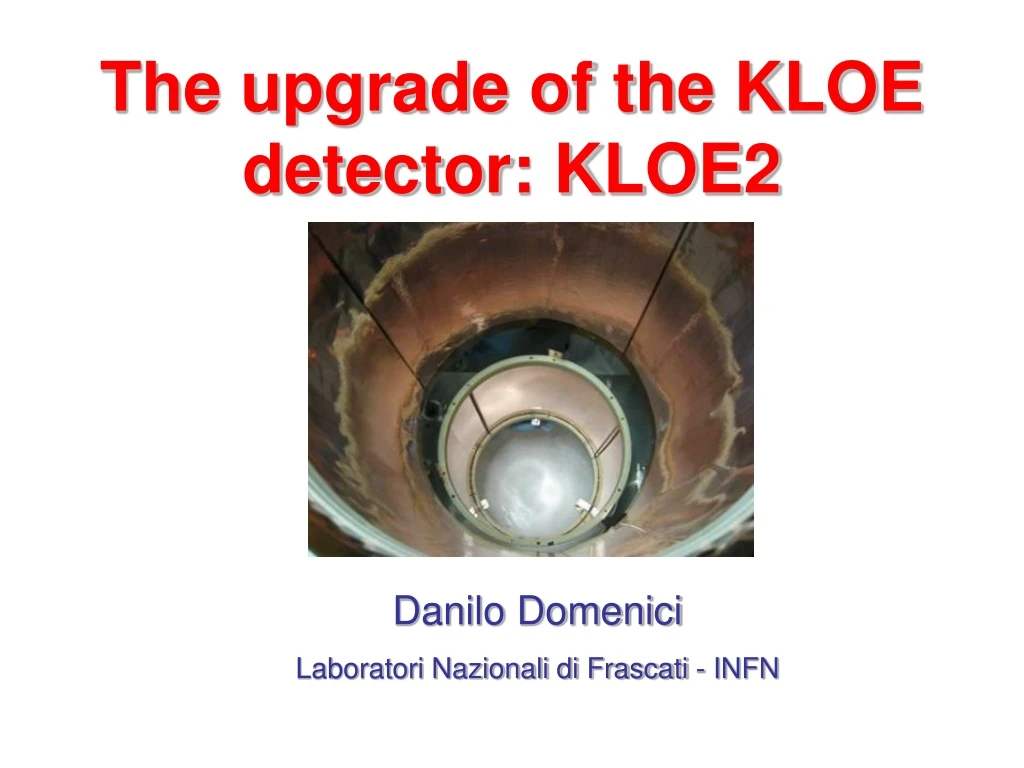
The upgrade of the KLOE detector: KLOE2 Danilo Domenici Laboratori Nazionali di Frascati - INFN
Overview • The Kloe detector • Kloe2 hardware upgrades • EMC new read-out • CCALand QCAL • γγ Tagger • Inner Tracker • Cylindrical GEM detector • 2006 Small Size Prototype • 2007 Full Size Prototype
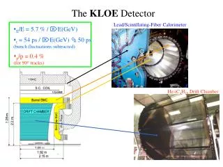
The KLOE detector Drift Chamber Calorimeter Multi-purpose detector optimized for Klong physics • Pb-Scintillating Fiber Calorimeter with excellent timing performance • 24 barrel modules, 4 m long and C-shaped End-Caps for 98% solid angle coverage • Time resolution: σT = 54 ps / √E(GeV) ⊕ 50 ps • Energy resolution:σE/E = 5.7% / √E(GeV) • Huge, transparent Drift Chamber in 5.2 kGauss field of a SC coil • Carbon fiber walls, 55000 stereo wires, 2 m radius, 4 m long, He/CO2 gas mixture • Momentum resolution: σ(pT)/pT ~ 0.4%
Kloe2 Highlights • Kloe2 will exploit the capability of DaΦne with the new Crab Waist interaction region (test starts in November 07) • 50 fb-1 are planned to be delivered in 34 years at the Φ peak energy for a vast physics program: significant sensitivities for the study of KS η and η’ rare decays, neutral kaon interferometry, lepton universality test will be reached • An option for a run at higher energy is foreseen (1< √s < 2.5 GeV) to accomplish multihadronic cross section measurements and γγ physics program • Expect to start experimental program before2010 • The apparatus will run with the present sub-detectors (Drift Chamber and Calorimeter), a reduced Magnetic field to enhance sensitivity for low-energy tracks, and some important hardware upgrades: • new read-out of Calorimeter • new small angle Calorimeter and QCAL • new γγ Tagger • new ultra-light Inner Tracker based onGEM technology
Calorimeter read-out Upgrade: MA-PMT • The MA PM option plans the substitution of the present phototubes with MultiAnode devices in order to improve the cluster resolution Standard PMT Multi-anode PMT Simulation of 2 beams of photons
13 23 50 cm Calorimeter read-out Upgrade: MA-PMT Hardware tests of Hamamatsu 8900 M16 • 12 M16 PM’s have been tested with laser light • We are now equipping an existing EMC prototype with the purpose of testing it with cosmics and beams to understand PMT response and to tune simulation of clustering with real data Side B 12 Hamamatsu 8900 192 cells 1.05x1.05 cm2 No r/o in macro-cells Side A 12 cells 4.2x4.2 cm2 + 2 macro cells R/o with standard PMs First multianode cell fully installed and under test with cosmics
Calorimeter read-out Upgrade: HQE-PMT • The HQE PM option plans the substitution of the presents Hamamatsu R5946 PM with the corresponding High Quantum Efficiency version • Advantages of a QE increase from 20% to 40%: • 30% time resolution increase • 30% Z spatial resolution increase • small energy resolution increase
Calorimeter read-out Upgrade: HQE-PMT Improvement in π/μ discrimination Improvement in low energy γ detection efficiency A calorimeter prototype is presently under study and will be soon tested at PSI
Calorimeter read-out Upgrade: the plan • We intend to continue R&D studies on both options up to summer 2008 • Both hardware performance and impact on physics must be fully assessed • A real plan for the EMC upgrade needs some more time and study to be fully elaborated: • HQE optionhas the unique advantage of avoiding any mechanical intervention on the calorimeter(~2 months installation time) but the devices are still in adevelopment stage and availability could be a problem wrt Kloe schedule • MultiAnodeoption would require an enormous installation effort, which could be afforded only if really worthwhile. The technique is however well established and easily commercially available
New Small Angle CCAL • The minimum angle to detect photons in the EMC end-caps increases from 8° to 18°, due to the new position of the Quads (at 25cm from IR) • The region in front of the Quads will be instrumented with a small angle Crystal Calorimeter (CCAL) to increase the acceptance for photons coming from KS and η decays • 300 ps resolution is needed to reject the machine background events • It is composed by two barrels per each side. The closest to IR module has a section of 2.5x2.5 cm2 and the other 1.5x1.5cm2. the lenght is 12cm. Thay are LYSO crystals (1.2cm X0) readout by APD
KS → π0π0 signal New Small Angle CCAL Impact of the Small Angle CCAL on KS → γγ Today Tomorrow with CCAL
New QCAL • Present QCAL is no more compatible with the new Quads position • A new one would allow to measure the impact position of the photons from the KL dacays in the DC. (KL→ 3π0 / KL→ 2π0 discrimination) • It is installed around the Quads, composed by a 1m long barrel of 12 sides and 5 cm thick, made of tiles of BC-408 (5x5cm2) and lead layers for a total of 5X0. The readout of the single tile is performed by WLS fibers (Kuraray Y11-200) coupled to SiPM
γγ Tagger • The tagger detector measures the displacement from the main orbit and the energy of scattered e+e- events (e+e- → e+e-γ*γ*→ e+e- X) • Two tagging stations are needed to obtain informations about the whole spectrum of electrons
PMT strip electronics e strip plastics γγ Tagger Each station is composed by modules of micro-strip Silicon detectors and plastic scintillator tile read-out by conventional PMT
tagger γγ Tagger proto in SIDDARTHA A prototype of the Tagger will be installed on the SIDDARTHA Interacion Region, in order to test the performance in terms of efficiency and machine background tolerance
Inner Tracker Available space for the insertion of the Inner Tracker inside the Drift Chamber
DC wall 25 cm 15 cm 60 cm DC wall Inner Tracker geometry • 5 independent Tracking Layers (L1-L5) • L1 radius 15 cm (limited by KLKS interference) • L5 radius 25 cm (limited by DC dimensions) Could cope with a different IR
IT simulation results Simulation results for a π track from KS → ππ pca: point of closest approach C1: Δx@pca: difference of x coord. between the pca of track wrt the vertex and the vertex C2: Δz@pca: difference of z coord. between the pca of track wrt the vertex and the vertex C3: Δpx@pca: difference of momentum px between the track at pca to the vertex and the vertex C4: Δx@vtx: sigma of the difference of x coord. between the reconstructed vertex and MC vertex
IT motivations and requirements • Optimization for the physics coming from the interaction region: fine vertex reconstruction of KS and η decay products • Detector requirements are: • σrφ ~ 200 µm; σz ~ 500 µmpoint space resolution • 5 kHz/cm2rate capability • Very low material budget< 1.5% X0 (large MS effect on low-energy tracks) A GEM Detector allows to easily fulfill the requirements a) and b) With the novel technology of Fully Cylindrical GEM an ultra-light detector can be built to fulfill the requirement c)
Advantages of a GEM Inner Tracker Peculiar features of the Cylindrical GEM • Ultra-light detector: only 3‰ X0 per layer all elecrodes are obtained from thin (50 μm) kapton foils coated with a copper layer (5 μm) • Dead zone free: inside the active area all the support mechanics is realized in fiberglass and placed at the edges of the cylinder. The structural rigidity is obtained by stretching the detector Common characteristics of GEM detectors • High gain uniformity: gain independent from mechanical tolerances of electrode positioning, depends only on GEM hole diameter precision (< 2μm) • Good spatial resolution: only limited by the number and type of electronics channels implemented (centre of gravity σ ~ 60 μm) • High rate capability: up to 50 MHz/cm2 measured • Good aging tolerance:2 C/cm2 integrated without damage and loss of performances
2 1 4 3 C-GEM building procedure 2. The GEM foil is rolled on a Aluminum mould coated with a machined Teflon film for a non-stick, low-friction surface 1. An epoxy glue is distributed along one edge of the GEM (~3 mm) 4. A perfectly cylindrical GEM is obtained 3. The cylinder is enveloped in a vacuum bag. Vacuum is applied with a Venturi system, providing a uniform pressure of 1 kg/cm2 With the same procedure Anode and Cathode are obtained
Small Size Prototype • In 2006 we built the very first C-GEM prototype using GEM foils from LHCb (∅ ~90mm, L ~ 250 mm) • Anode and cathode were realized with the basic material used for the GEMs (50 µm kapton with 5 µm Cu deposition on one face • cylindrical electrodes are inserted one into the other (cathode, GEM-1,2,3, anode) and then flanges are glued with araldite 2011 • after the assembling, the C-GEM has been installed in a stretching system, equipped with a gauge meter allowing the monitoring and control of the mechanical tension applied
Test with X-rays • the detector, operated with Ar/CO2 = 70/30 gas mixture, has been tested in current mode (no FEE, no segmentation of readout) and fully characterized with an X-ray gun( 6 keV) Gas gain • Detector stability has been checked up to a gas gain of 104 • no dependence of the detector performance from the mechanical stretching tension observed in the range 2 ÷ 12 kg/electrode (100 ÷ 700 g/cm)
Full size L1 C-GEM prototype • At the beginning of 2007 the construction of a Full Size Prototype has started • The dimensions are similar to those of the IT Layer1: same diameter 300 mm Ø, but reduced 352 mmactive length • All electrodes obtained as a join of 3 foils (planar gluing) • GEM size: 450x1000 mm2 (single foil 450x333 mm2) • Anode readout with 1538 strips and 650 µm pitch (only rφ coordinate) • FEE based on CARIOCA-GEM chip (amplificator/shaper/discriminator) • Fiberglass support mechanics out of the active region (Permaglass)
Gas inlet detail Permaglass support flanges Annular flanges out of the active area support the detector Flat edges on the anode for FEE bonding Permaglass annular flanges
Cylindrical Cathode annular flange 3 foils joined together
Cylindrical GEMs Foils are preliminary tested in a humidity controlled box (20 independent sectors) 3 foils are planary glued 3 mm overlap region
Anode read-out 650 µm pitch 500 µm pitch Detail of the read-out flaps to bond FEE
Assembly tool GEM1 A vertical insertion system with very precise mechanics and linear bearing equipments is used to insert the electrodes cathode
Final view with FEE mounted Each FEE slot hosts 4 CARIOCA-GEM chips, for 32 channels readout Output signal connections Front-End faraday-cage Kapton bonding flaps for input signal connection (ZIF connector)
Conclusions • The Kloe detector is ready to take up the challenge given by the next 50 fb-1delivered by the new DaΦne • Hardware upgrades are foreseen to reduce systematics and open new physics channels • A new read-out for the EMC, and the new CCAL and QCAL will improve the γ detecion efficiency • A new Tagger will open the way to profitable γγ physics • A new Inner Tracker will be inserted to improve the vertex reconstruction for the physics near the IR (mainly KS and η) • The IT is based on the innovative technology of fully Cylindrical GEM detectors (C-GEM)
KLOE-2 roll-in proposal Abbiamo in seguito preparato una lettera per descrivere la nostra proposta, sottoposta all’attenzione del Laboratorio il 5 Settembre Essa e’ disponibile sul nostro sito web (www.lnf.infn.it/kloe/kloe2). Diventera’ una nota interna LNF a breve. In essa proponiamo di effettuare il roll-in di KLOE-2in due fasi: • Step 0 : Da effettuarsi a fine 2008. Roll-in del rivelatore attuale con gli upgrade minimi necessari per un run sicuro ed efficiente • Step 1: Da effettuarsi probabilmente a fine 2009. Implementazione degli upgrades piu’ ambiziosi con il goal di una campagna di presa dati piu’ lunga
Roll-in Proposal • The Kloe roll-in will be performed in 2 steps: • Step 0 : take place at end of 2008. Roll-in of the present detector with the minimal upgrades for a reliable and efficient run • Step 1: take place possibly at end 2009. Implementation of all the hardware upgrades aiming to a long period data taking
Read-out Anode 2 mm GEM 3 2 mm GEM 2 2 mm GEM 1 3 mm Cathode Cathode Conversion & Drift 3 mm GEM 1 Transfer 1 2 mm GEM 2 Transfer 2 2 mm Induction GEM 3 Induction 2 mm Transfer 2 Anode Transfer 1 Read-out Conversion & Drift Principle of operation of a GEM • A GEM (Gas Electron Multiplier) (F.Sauli NIM A386, 1997) is a 50 µm thick Kapton foil, copper clad on both sides, perforated with an array of holes (70 µm diameter, 140 µm pitch) • If 300-400 V are applied between the two sides, a ~100 kV/cm electric field is produced inside the hole, high enough to start an avalanche multiplication • Gains of 102 are safely obtained with a single foil. Usually 3 foils are placed in a cascade (Triple-GEM) with gains up to 106 A Triple-GEM detector is obtained inserting 3 GEM foils between a Cathode and an Anode/Read-out A Cylindrical Triple-GEM detector is obtained inserting one into the other the 5 cylindrical electrodes
40° 650 650 C-GEM Read-out scheme • The cylindrical Anode is segmented with a 2-D set of X-V strips providing point space measurement • X strips read-out from above • V strips read-out from below and partially from above • Xpitch = Vpitch = 650 µm • XV angle = 40° • Resolutions: σrφ ~ 190 µm; σz ~ 370 µm X and V strips are engraved on the same kapton plane V strips are connected with electrical vias
Test results: electron transparency • Typical curves for electron transparency vs drift, transfer and induction fields are the “fingerprint” of a GEM • Results are in perfect agreement with those obtained with • planar triple-GEM operated with the same gas mixture Is=anode current Id=cathode current I3d=current on the bottom side of the third GEM
Simulation of the GEM glued junction line • the ~3mm overlap kapton region has been simulated (Maxwell+Garfield) • the effect is a distortion of the field caused by space-charge • electrons are anyway focused towards the multiplication holes of the GEM • the efficiency for a MIP crossing @90° the middle of the overlap slightly drops from 100% to ~98%
Al Cylindrical Moulds Teflon coated The GEM foils are rolled on Aluminium cylindrical moulds coated with a machined Teflon sheet, for a non-stick, low friction surface 5 different moulds for the different diameters of the 5 electrodes
Planar gluing and rolling tool The tool allows to work in parallel with planar gluing and rolling GEM is rolled and enveloped in a vacuum bag
Front-End Electronics • FEE for Full Size Prototype based on the 8 channel CARIOCA-GEM chip (LHCb Muon System), uses 2 boards: • a Motherboard bond to the detector with ZIF connectors hosting regulators and I/O connectors • a 32 channels Daughterboard hosting 4 CARIOCA chips • FEE for Full Size Prototype based on CARIOCA-GEM chip • Design of a Motherboard bond to the detector with ZIF connectors carrying I/O signals and controls • Design of a Daughterboard hosting the chip • FEE for final Inner Tracker based on dedicated 64 channels ASIC chip (GASTONE) with serial read-out, uses 2 boards • the same Motherboard for CARIOCA can be used • a new 64 Daughterboard hosting the GASTONE chip
Support and Stretching system • The detector is finally mounted on a support system and longitudinally stretched with a tension of ~200 g/cm • It can be easily transported on a test-beam Tension gauge meter