Advanced Upgrade of Front-End Electronics for nSYNC in High-Energy Physics Experiments
This document presents a comprehensive outline of the upgraded front-end electronics for the nSYNC project, detailing the implementation of the ODE system at the INFN Cagliari. Highlighted features include 192 LVDS input signals, advanced synchronization chips, and a sophisticated trigger interface. The design utilizes 10-layer motherboards, enhanced clock management, and supports high data rates for TDC and DAQ interfaces. The architecture ensures flexibility in integration while maintaining a user-friendly "plug & play" setup, optimizing link management for efficient data processing.

Advanced Upgrade of Front-End Electronics for nSYNC in High-Energy Physics Experiments
E N D
Presentation Transcript
Outline • Present schemes and features • New schemes of nSYNC • Technology S. Cadeddu - INFN Cagliari
Present ODE implementation SYNC L0 front-end electronics stage • 192 LVDS input signals • 24 SYNC chips (on 3 types of piggy board) TFC system interface and clock management • 1 optical receiver + 1 TTCrx chip • 1 QPLL chip • Tree network based on MC100LVEP family L0 trigger interface • 12 GOL chips + 1 parallel optical transmitter • Valid data transmission @40MHz L1 DAQ interface • 1 GOL chip + 1 VCSel diode • Valid data transmission @1 MHz FPGA board controller • Flash RAM based Actel FPGA (ProAsicPlus) • 3 buses (32 bit) for SYNC and GOL interfaces ECS interface • 1 ELMB board • CANbus link on the backplane • 2 I2C internal buses 6U Compact PCI card • 10 layers motherboard with controlled impedance • Mixed 5/3.3/2.5 V devices Controller DAQ inter. ECS inter. TRG inter. TFC inter. GOL S. Cadeddu - INFN Cagliari
Present SYNC implementation • TDC & Synchronizer: • 4 bit TDC (1.5 ns resolution @ 40 MHz) – DLL based. Custom Macro-cell. • L0 Trigger Interface: • Sends 8 synchronized hits along with the 2 LSB of the BX Id @ 40 MHz. • Prog. buffer depth • L0 buffer & Derandomizer: • Based on the 128x27 SRAM blocks (CERN development – K. Kouklinas) • Circular buffer of 256x54 SRAM. • Initial R/W address programmable. • FIFO of 128x54 SRAM • The depth is programmable to 16, 32, 64 or 128. • EDAC: • Single Error detection and correction, Double Error detection. 7 bits code. • Histogram Builder: • 16 bins of 224 entries each. • I2C Interface • Used to R/W internal configuration. • Configuration Registers are triple voted and auto-corrected for best SEU immunity. • All other registers are triple voted • Trigger link test • L1 link test S. Cadeddu - INFN Cagliari
SYNC 1.0: The present … 8 LVDS Input I2C I2C • SYNC 1.0 • 97 pins • 4x4 mm2 • QFP 14x14 100 pins • IBM 0.25 mm RadHard VDD GND VDD VDD GND GND TDC’s I2C L0 Buffers L0 Buffers GND VDD GND GOL output VDD CTRLS L0 Buffers L0 Buffers GND VDD Derand Derand GND VDD VDD GND Output to L1 electronics S. Cadeddu - INFN Cagliari
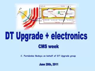
ODE upgrade specs • Design new boards (nODE), almost “plug & play” with current ODEs • No need to touch cables from chamber to crates • Same transition boards (no crate re-cabling) • Single type of board for all stations/regions • Use new GBT and versatile link components to implement trigger, DAQ, TFC and ECS interfaces • Optimized number of links to the L0 Muon trigger • Maintain the trigger unit information on the same link • Possible implementation in the TELL40 • Read TDC data @ 40 MHz rate • No more need to maintain present TFC and ECS systems • Use a new custom ASIC (nSYNC) to integrate all the required functionalities • Clock synchronization and Bx alignment • Time measurements and histogram capability • Zero suppression algorithm and buffering • Test facilities and diagnostic • Trigger, DAQ, TFC and ECS interfaces via GBTx • Guarantee enough flexibility to increase granularity and reduce channel occupancy • Possible IB boards replacement in the high occupancy zone • Possible chambers replacement in low granularity zone S. Cadeddu - INFN Cagliari
nODEArchitecture nSYNC nSYNC nSYNC nSYNC nSYNC nSYNC nODE GBT interf. GBT interf. GBT interf. GBT interf. GBT interf. GBT interf. DATA Path Hit format Hit format Hit format Hit format Hit format Hit format Sync Sync Sync Sync Sync Sync To Trigger links simplex Hist. Hist. Hist. Hist. Hist. Hist. GBTx Hit data serializer 192 Input channels GBTx HIT data serializer Bunch cross synchr. Bunch cross synchr. Bunch cross synchr. Bunch cross synchr. Bunch cross synchr. Bunch cross synchr. VTTxOptical transmitter LVDS Receivers Translators LVDS Receivers Translators LVDS Receivers Translators TDC TDC TDC TDC TDC TDC LVDS Receivers Translators LVDS Receivers Translators LVDS Receivers Translators GBT interf. GBT interf. GBT interf. GBT interf. GBT interf. GBT interf. Zero Supp. Zero Supp. Zero Supp. Zero Supp. Zero Supp. Zero Supp. To TELL40 Links simplex GBTx Hit data serializer GBTx TDC data serializer VTTxOptical transmitter To/from TFC 1 link duplex ECS/TFC Clock management GBT-SCA Control Monitor GBTx Data Ser/Des VTRx Optical transceiver Phase adjust Clock driver Power section Power up sequencer DC/DC converter Voltage regulators S. Cadeddu - INFN Cagliari
nSYNCArchitecture • TDC + Histogram builder: • 4 bit TDC (1.5 ns resolution @ 40 MHz) • 16 bins of 224 entries each. The counts stop when any of the bins saturates. Dead time free in hit capture. • Muon Trigger TELL40 Interface: • Sends synchronized hits every machine cycle (40 MHz). • Prog. buffer depth to guarantee the synchronization between different nSYNC sending data through the same GBT • TDC ZS: • Zero Suppression of TDC’s data not related to hit events. • TDC TELL40 Interface: • Sends synchronized ZS TDC data every machine cycle (40 MHz). • Prog. buffer depth to guarantee the synchronization between different nSYNC sending data through the same GBT • I2C Interface: • Configure through the ECS. • Triple-voted configuration S. Cadeddu - INFN Cagliari
SYNC 1.0 vs nSYNC 8 ch vs 32 ch Histoforeach TDC No more needsfor RAM’s + EDAC TDC data ZS 97 pins vs 220 pins S. Cadeddu - INFN Cagliari
Whyanasic • Modularity: we are thinking at three possible modularity (32, 48, 96 channels), to best fit the requirements for: • Power consumptions (less then 20mA per channel) • Best ZS for TDC data • An eye on LS3 stage: If we go to design a new detector with higher granularity for at least M2R1 and M2R2 (and maybe for the same regions of M3 too), we have also to design a new front-end electronics and a new front-end board where we can integrate the nSYNC direct on the detector. S. Cadeddu - INFN Cagliari
Technologies IMEC DARE (Design Against Radiation Effects) technology: • Radiation-hardened-by-design libraries in standard commercial technology • DARE180 well supported (UMC .18) • DARE90 small core & IO library available(UMC 90nm) • Manufacturing, Packaging, Testing, Characterization (lot) Qualification & Radiation test up to FM is supported by imec’s ASIC Services • Through subcontractors (Microtest, Maser, MAPRAD) • Flexible solution • DARE allows for mixed signal design • Can add specific analog blocks; designed by customer, design house or imec • Encrypted models of library cells can be used in analog design ervironment. • Cells can be added to the library • IO pads can be customized ... • Imec has expertise on the full DSM design flow • They tested DARE digital blocks up to 1 MRad without failures or leakage current increases. • SEU performance is in the order of a LET cross-section of 48/60 Mev. S. Cadeddu - INFN Cagliari
Technologies DARE UMC 180 Family pads: - 70x70 - 110x110 - custom IO at 3.3 and 2.5 V All FF’s have scan equivalents + Fillers & Corners + Customer Requests + Additional Analog IP developed by an external design house (DAC, ADC, ...) S. Cadeddu - INFN Cagliari
nSYNC: work in progress I2C interface: • Designed and tested in another chip for a INFN gruppo 5 experiments. PLL and Delaylines: • These are the maincrucialpartsfor the TDC implementationaswellas the GBT interfacesthatneeds a differentfrequenciesfrom the master clock.They are under study and develpment in another INFN gruppo 5 experiment (alldigitall) S. Cadeddu - INFN Cagliari
AllDigital PLL • An ADPLL include a DCO insteadof a VCO • In mostarchitecture the DCO=DAC+VCO • In other case the DCO isbased on effectsofanalogcomponents • The aimof ALLDIGITALL experimentistorealize a true DCO, portable on differenttechnologies (FPGA, ASIC), integrable in a flow fullydigital S. Cadeddu - INFN Cagliari
DCO in 130nm technology S. Cadeddu - INFN Cagliari
DCO in 130nm technology S. Cadeddu - INFN Cagliari