Download
1 / 38
380 likes | 402 Vues
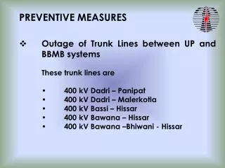
Explore signal integrity analysis, EM compatibility, and dependability in the LHC Beam Interlock System. Learn about types of signals, simulation results, rules for designs, preventive measures, and test outcomes.

E N D
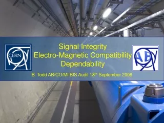
1. Signal Integrity Analysis • The five types of signals • Simulation results • Rules for designs 2. Electro-Magnetic Compatibility • The different link types • Preventive measures • Test results 3. Dependability Analysis • FMECA method • Results • Conclusions LHC Beam Interlock System
1. Signal Integrity Analysis • The five types of signals • Simulation results • Rules for designs 2. Electro-Magnetic Compatibility • The different link types • Preventive measures • Test results 3. Dependability Analysis • FMECA method • Results • Conclusions LHC Beam Interlock System
Signal Integrity Analysis • Five different types of signal in the BIS… • Current Loops from CIBU to User System (<4m) • RS485 Channels from CIBU to BIC (<1200m) • Single Mode 1310nm Fibre Optic Links (<6000m) LHC Beam Interlock System
Signal Integrity Analysis Five different types of signal in the BIS… 4. RS485 Channels internal to BIC (<1m) 5. TTL or LVTTL signals on a board (<15cm) LHC Beam Interlock System
Fundamental Properties Five different types of signal in the BIS… Type-1 : Current Loops from CIBU to User System (<4m) - DC mode Type-2 :Channels from CIBU to BIC (<1200m) - DC modefor critical 62.5khz for data Type-3 :Single Mode 1310nm Fibre Optic Links (<6000m) – 8 – 8.192 – 10MHz Type-4 :RS485 Channels internal to BIC (<1m) - DC modeor 250kHz data Type-5 :TTL or LVTTL signals on a board (<15cm) – Clocks, Data, Flags Rules: 3W rule for cross talk Sheilded Twisted Pair 90-Ohm CERN NE12 Ground Planes, Power Planes, UNINTERRUPTED! Long links have similar impedances 50-200 Ohm (not controlled though) Slew-rate limited signals where possible LHC Beam Interlock System
PCB principles LHC Beam Interlock System
Type-1 Integrity Current Loops from CIBU to User System (<4m) VUSER Current Regulator Switch Simple Circuit… Switched Current Loop Switch can be a relay or transistor Vuser can be 5-24V BEAM_PERMIT_INFO similar – slow optocoupler = ~100us to change LHC Beam Interlock System
Type-2 Integrity RS485 Channels from CIBU to BIC (<1200m) (Slew-Rate Limited Transceivers) Electrical length = 10.6 (I can explain…) i.e. High Frequency, so impedance has to be considered All the links in every configuration will work acceptably!! LHC Beam Interlock System
Type-3 Integrity Single Mode 1310nm Fibre Optic Links (<6000m) Optical – EMC is not an issue LHC Beam Interlock System
Type-4 Integrity RS485 Channels internal to BIC (<1m) (Slew-Rate Limited Transceivers) Consider the Safe Beam Flag that is transmitted through the Patch Panels and Extenders LHC SPS All the signals like this have an electrical length <<0.05… NO PROBLEM! LHC Beam Interlock System
Type-5 Integrity TTL or LVTTL signals on a board (<15cm) Electrical Length <0.05… Look up table created: All OK! Biggest constraint on CIBO – Output = 1.1ns rise time so <3cm From AD8611 O/P to CPLD LHC Beam Interlock System
1. Signal Integrity Analysis • The five types of signals • Simulation results • Rules for designs 2. Electro-Magnetic Compatibility • The different link types • Preventive measures • Test results 3. Dependability Analysis • FMECA method • Results • Conclusions LHC Beam Interlock System
Electro Magnetic Compatibility Rules: Power Planes and Ground Planes, Grounded copper pours everywhere! Ground = Earth = Chassis = 0V ESD pins on Front Panels ESD strips on VME PCBs Transient Voltage Suppressors on ALL links that leave an enclosure Sheilded (360-degrees) twisted pairs, with dedicated ground wires inter-system LHC Beam Interlock System
Electro Magnetic Compatibility The idea is: This system is rock solid for EMC Test it to the HIGHEST EMC levels (industrial 4.0kv same as power systems) Set an example for others using modern techniques NOT the same as LEP No fear to implement traditionally unaccepted principles. LHC Beam Interlock System
TT40 BIC in BA4… LHC Beam Interlock System
Testing Criteria Tests according to the IEC-61000 for electrical systems: Ideally: A at 4.0kV Results categorised into four different types: Unsafety 1. User Permit set to FALSE = see if EMC makes it TRUE 2. User Permit set to TRUE = see if EMC makes it FALSE False dumps LHC Beam Interlock System
Recommended Interconnect CIBU to Controller LHC Beam Interlock System
CIBU to Controller 1/2 Cable with FULL Shields FULL Grounds Results . LHC Beam Interlock System
CIBU to Controller 2/2 Cable with FULL Shields NO Grounds Results . LHC Beam Interlock System
Recommended Interconnect User System to CIBU LHC Beam Interlock System
User System to CIBU 1/3 Cable with FULL Shields FULL Grounds Results . LHC Beam Interlock System
User System to CIBU 2/3 Cable with Pig-tail Shield No Grounds Results Power PC Crashed – Ethernet Controller Stopped responding LHC Beam Interlock System
User System to CIBU 3/3 Cable with One Pig-tail Shield No Grounds Glitches recorded in History Buffer Permit FALSE on each salvo Permit TRUE on each salvo LHC Beam Interlock System
VME Power Supply VME PSU, Specified as “IEC-61000 Tested” Results LHC Beam Interlock System
CIBU Power Supply CIBU PSU (CIBD), Specified as “IEC-61000 1kV” Supply has been double encased, and has mains filter Results Power PC Crashed – Ethernet Controller Stopped responding, SW Permit FALSE LHC Beam Interlock System
Electro Magnetic Compatibility The idea is: This system is rock solid for EMC Test it to the HIGHEST EMC levels (industrial 4.0kv same as power systems) Set an example for others using modern techniques NOT the same as LEP No fear to implement traditionally unaccepted principles. No problem – written a specification for User System interface to the BIS Will be approved in collaboration with User Systems… and we’re in business for 2007 LHC Beam Interlock System
1. Signal Integrity Analysis • The five types of signals • Simulation results • Rules for designs 2. Electro-Magnetic Compatibility • The different link types • Preventive measures • Test results 3. Dependability Analysis • FMECA method • Results • Conclusions LHC Beam Interlock System
FMECA • The defined safety of the MPS is based on IEC61508 • Define losses NOT in human life, but machine downtime & repair cost • -If the LHC is not protected properly, it is considered a catastrophic failure will happen in 20 years operation Combined MPS Safety LHC Beam Interlock System
So… SIL3 or better?? = FMECA Failure Modes, Effects and Criticality Analysis In what way can something go wrong?… …when it does go wrong, what happens to the system?… …and just how much of a problem does this cause? LHC Beam Interlock System
FMECA FMECA starts at the Component Level of a system MIL-STD-1629 Break a large system into blocks, defining smaller, manageable sub-systems get subsystem schematics, component list, and understand what it does MIL-HDBK-338 MIL-HDBK-217 get MTBF of each component on the list, derive PFAIL(mission) MIL-HDBK-338 FMD-97 derive failure modes and failure mode ratios for each component explain the effect of each failure mode on both the subsystem and system determine the probability of each failure mode happening. Draw conclusions! LHC Beam Interlock System
FMECA Bill of Materials MIL-HDBK-217F or manufacturer FMD-97 MIL-HDBK-338 LHC Beam Interlock System
FMECA Schematic multiply through Designer Knowledge MIL-HDBK-338 LHC Beam Interlock System
FMECA Since there are NO single points of failure, double failures have been considered to deriveBF LHC Beam Interlock System
FMECA SIL 4 1% of all fills are lost due to a failure of the BIS LHC Beam Interlock System
Extrapolating… Hourly rate is based on MIL, Manufacturer etc. Extrapolation is non-trivial, whole MPS FMECA approach to be verified by another PhD! LHC Beam Interlock System
FIN LHC Beam Interlock System
ELECTRICAL LENGTH • The equivalent frequency of this signal can be found from the equation: • This means that the 200ns rise-time has an equivalent frequency of 1.6MHz, the wavelength of such a signal is defined by: • Tests reveal thatthe wave propagation velocity (v) is approximately half the speed of light in a vacuum (c) in the NE12 Cable from User Interface to Controller case, leading to a wavelength definition of: • This leads to a wavelength of 112.5m, now the ‘electrical length’ of the signal is defined as: • The longest length (l) expected in the machine is around 1200m, applying this yields an electrical length of 10.6, this is well above the limit for low-frequency design, as an electrical length greater than 0.05 has to be treated as high-frequency LHC Beam Interlock System