Download
1 / 9
90 likes | 203 Vues
Learn about the meticulous process involved in providing precise magnetic field maps for the ATLAS Inner Detector at CERN, essential for defining momentum scales of tracks. Detailed work with sensors, pneumatic motors, and NMR probes ensures accurate calibration and corrections to achieve required accuracy.

E N D
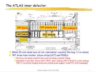
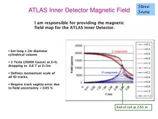
Steve Snow ATLAS Inner Detector Magnetic Field I am responsible for providing the magnetic field map for the ATLAS Inner Detector. • 6m long x 2m diametercylindrical volume • 2 Tesla (20000 Gauss) at Z=0, dropping to 0.8 T at Z=3m • Defines momentum scale of all ID tracks. • Require track sagitta error due to field uncertainty < 0.05 % End of coil at 2.65 m
2006the key year of the mapping project Years of thinking and preparation: I started back in 1997 Months of building and installing the mapping machine CERN team: Martin Aleksa, Felix Bergsma, Pierre-Ange Giudici, Antoine Kehrli, Marcello Losasso, Xavier Pons, Heidi Sandaker, started mid 2005 5 days of data taking, 2nd to 7th August. Maps at 5000, 7000, 7730 and 8000 Amps. Months of data analysis (John Hart, Paul Miyagawa, SS) now nearing completion.
The Mapping Machine Cards each hold 3 orthogonal sensors Pneumatic motors with optical encoders. Move and measure in Z and φ. 4 arms in windmill. Each arm equipped with 12 Hall cards 4 fixed NMR probes at Z=0
Typical data from 5kA map Typical Bz, Br and Bf values from probes 3,6,9,12 (increasing radius) on arm AE. Bz peaks at ~13000 G. Br peaks at ~4500 G, Bf ~0 except for return conductor at 90 deg.
Surveys A lot of them ! We need to know precisely where the sensors are Typical accuracy 0.2 mm Survey of mapping machine in Building 164 . Radial positions of Hall cards Z separation between arms Z thickness of arms Survey and re-survey in situ before mapping. Survey again in situ after mapping. Position and rotation axis of each arm Position of encoder zero Position of NMR probes All these in the Inner Warm Vessel co-ordinate system Survey of rail slope in IWV Survey the offsets of 3 Hall sensors from a common point in the card Final map will be in IWV system, as will SCT TRT final survey
Calibration Hall sensors Low field calibration , up to 1.4 T, good to ~2 G High field calibration, up to 2.4 T, good to ~10 G NMR probes Need no calibration (was done by whoever measured Gp = 42.57608 MHz/T ) Compare proton resonance frequency with reference oscillator, accurate to 0.1 G.
Corrections derived from the data Corrections to Hall probes normalisation and angular alignment can be derived from the data assuming: + Field obeys Maxwell + Approximate phi symmetry + No high spatial frequencies Normalisation corrections are small, as expected from probe calibration Alignment corrections have spread of ~2 mrad, as expected from limited Hall card mounting accuracy. Corrections for the field due to magnetic components of the machine. Perturbations visible in the data, eg this phi scan → Correlated with identifiable componenets. We subtract a dipole field, located at component position, with dipole strength chosen to make residuals look smooth. Phi encoder
Conductor geometry model All based on surveys of solenoid as built, except weld thickness chosen to fit field map data Fitting function 95% of the field is directly due to the solenoid current. Use conductor geometry model and integrate Biot-Savart law. 7 free parameters: scale factor and aspect ratio (Length/Diameter) of conductor model Position and orientation of field due to conductor 5% of the field is due to magnetised iron (TileCal, girders , shielding disks etc). For the moment use 4 free parameters: Fourier-Bessel series
Results R.M.S. residuals of fit to 5000A data are Br 3.8, Bz 3.9, Bφ 3.2 Gauss R.M.S. residuals of fit to 7730A data are Br 7.6, Bz 7.1, Bφ 5.7 Gauss We expect to exceed the required accuracy of 10 Gauss The fit tells us that solenoid axis is 2 mm below IWV axis; the barrel tracker has been placed 2 mm low to match.