Download
1 / 27
290 likes | 496 Vues
Track-based alignment of the ATLAS Inner Detector. Sergio Gonzalez-Sevilla Instituto de Física Corpuscular (IFIC). On behalf of the ATLAS Inner Detector Alignment group. CHEP 07 2-7 September 07 Victoria, BC (Canada). The ATLAS experiment. Muon Spectrometer. Calorimetry System.

E N D
Track-based alignment of the ATLAS Inner Detector Sergio Gonzalez-Sevilla Instituto de Física Corpuscular (IFIC) On behalf of the ATLAS Inner Detector Alignment group CHEP 07 2-7 September 07 Victoria, BC (Canada)
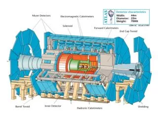
The ATLAS experiment Muon Spectrometer Calorimetry System Inner Detector Sergio Gonzalez-Sevilla - 5 Sep 07 - CHEP07 (Victoria)
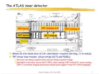
ATLAS Inner Detector ~5.60 m Semiconductor Tracker Pixel detector ~2.30 m Transition Radiation Tracker Sergio Gonzalez-Sevilla - 5 Sep 07 - CHEP07 (Victoria)
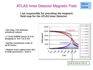
Inner Detector alignment requirements • Physics motivations of the Inner Detector alignment requirements: • track parameters resolutions degraded < 20% by misalignments • systematic error M(W) < 15 MeV/c2 • b-tagging, secondary vertices, etc… • alignment controlled to O(10) mm or better • Initial knowledge of the detector and hardware-based alignment: • Mounting and Survey measurements: • assembly measurements during detectors production • survey in assembly area and pit (eg: photogrammetric measurements elliptical shapes in SCT barrels) • precisions: O(100) mm • Frequency Scanning Interferometry (FSI): • continous monitoring during ATLAS data-taking • deformations in shapes of mechanical structures (environmental cond.) • precisions: O(10) mm (3D points) • Ultimate precisions reached with track-based alignment algorithms • Challenge: 6 degrees of freedom (dofs) / module entire system is ~36k dofs ! Sergio Gonzalez-Sevilla - 5 Sep 07 - CHEP07 (Victoria)
Minimization of c2: (inverse) covariance matrix residuals Alignment approaches (1/2) • Several approaches to silicon (Pixel and SCT) and TRT alignment: • relative alignment of the TRT wrt silicon by track extrapolation • implementation of combined alignment silicon+TRT (momentum constraint) • Algorithms implementations in the ATLAS software framework (Athena): • Robust: • centre residuals and overlap residuals • 2-3 dofs, many iterations • alignment corrections computed without minimizations • Global c2: • in-plane residuals • 6 dofs, few iterations • large linear system (35k x 35k) • correlations accounted though internal track refit • Local c2: • distance of closest approach • 6 dofs, many iterations • 6x6 matrices (module level) • correlations through iterating • TRTAlignAlg: • local and global approaches • calibrations required (TRT drift-time relations) Sergio Gonzalez-Sevilla - 5 Sep 07 - CHEP07 (Victoria)
Tracks • Digits • Raw Data Alignment Algorithm Reconstruction Iteration until convergence Alignment Constants Final Alignment Constants Alignment approaches (2/2) • Iterative algorithms: • integration into the ATLAS offline software chain • alternate computation of alignment corrections and track fitting • Solving a large system of linear equations: • limiting factors: size, precision and execution time • fast methods: • sparse matrices • MA27 less than 10 mins for 35k in a single CPU) • 64-bits parallel processing: • dense matrices(e.g. vertex constraint) • ScalaPack 10 mins. for full Pixel system (12.5k) on 16 nodes (diagonalisation) Sergio Gonzalez-Sevilla - 5 Sep 07 - CHEP07 (Victoria)
Alignment infrastructure • Detector description in terms of geometrical primitives (GeoModel) • Logical volumes grouped in hierarchical nodes • Alignment infrastructure based on alignable nodes • Three different levels: • level 1: entire subdetectors (whole Pixel, SCT & TRT barrel and end-caps) • level 2: silicon layers & disks, TRT modules • level 3: silicon modules (individual straw displacements foreseen) Sergio Gonzalez-Sevilla - 5 Sep 07 - CHEP07 (Victoria)
Algorithms validation : CTB • Combined Testbeam (2004) • ATLAS barrel slice detectors from all different ATLAS subsystems • Data-taking program: • e, p, m, g ; 2 up to 180 GeV/c • without and with B-field (1.4 T) • ~20M validated events for the ID TRT SCT Pixels m = 1 mm s = 12 mm m = 0.5 mm s = 22 mm Pixel SCT Robust alignment
5 mm SR1 Cosmics (1/2) • Combined SCT+TRT cosmic runs in SR1 surface assembly area (2006) • Scintillators trigger, no B-field MCS @ low p • Barrel sectors: 22% SCT, 13% TRT • ~400k events recorded SCT TRT m SCT residuals Sergio Gonzalez-Sevilla - 5 Sep 07 - CHEP07 (Victoria)
TRTAlignAlg (global) SCT EC disk alignment SR1 Cosmics (2/2) • Alignment improves SCT hit efficiency ! usage of survey information nominal positions Sergio Gonzalez-Sevilla - 5 Sep 07 - CHEP07 (Victoria)
MISALIGNED (x100) Y X Z CSC and CDC • Computing System Commissioning (CSC) and Calibration Data Challenge (CDC) • Simulation of calibration and physics samples • Testing the ATLAS software chain (computing model) • calibration and alignment procedures • Realistic detector description: • misalignments at all levels (translations+rotations) • shifted and rotated magnetic field • extra-material Sergio Gonzalez-Sevilla - 5 Sep 07 - CHEP07 (Victoria)
dx (mm) Robust Iteration Convergence and residuals with CSC • Multimuon sample: • 10 muons/event • sxy = 15 mm ; sz = 56 mm • Momentum spectrum : [2; 50 ] GeV/c • Algorithms converging, residuals ok Perfect Iteration 4 Global c2 TRT layer 0 m = 1 mm s = 12 mm As-built TRTAlignAlg Sergio Gonzalez-Sevilla - 5 Sep 07 - CHEP07 (Victoria)
Global deformations and weak modes • Sagitta distortions (weak modes) • Bias in track parameters but helical path mantained ! • tracks c2 (almost) blind to global deformations Momentum asymmetry Global c2 (level 3 alignment)
Beamspot offset and d0 vs f0 • Effect of global distortions: beamspot offset (primary vertex displaced) • (transverse impact parameter) (azimuthal angle) dependence Y x
Removing global distortions • Make use of all available information: • redundant measurements: • momentum measurement in the Muon Spectrometer • E/p relation from Calorimeters • external constraints (survey, FSI, common vertex, mass constraint, etc.) • different event topologies (cosmics, beam halo, etc.) After alignment Beamspot offset corrected As-built Global c2 Multimuons + cosmics Sergio Gonzalez-Sevilla - 5 Sep 07 - CHEP07 (Victoria)
Summary • Track-based alignment is required to help reaching the optimal performance of the experiment • Different alignment algorithms implemented under the ATLAS software framework (Athena) • Validation performed with simulation and CTB and Cosmics real data • CSC and CDC Challenges with a realistic detector description • Biases in track parameters from sagitta distortions • control and minimize their effects • importance of higher levels macro-structures alignment Many thanks to the whole ATLAS Inner Detector alignment community !! Sergio Gonzalez-Sevilla - 5 Sep 07 - CHEP07 (Victoria)
Status of the ID installation • All Inner Detector systems (Barrel, EC-A and C) already installed !! • Installation and commissioning of services ID EC-A (May 2007) • Survey of the detectors positioning on surface and down in the pit • Shifts O(mm) between subsystems: • ID aligned <1 mm to the solenoid B-field axis • EC’s shifts ~3 mm in z (thermal enclosures constraints) Sergio Gonzalez-Sevilla - 5 Sep 07 - CHEP07 (Victoria)
track Intrinsic measurement error + MCS hit residual Key relation! Pawel Bruckman The Global c2 approach The method consists of minimizing the giant 2resulting from a simultaneous fit of all particle trajectories and alignment parameters: Let us consequently use the linear expansion (we assume all second order derivatives are negligible). The track fit is solved by: while the alignment parameters are given by: Sergio Gonzalez-Sevilla - 5 Sep 07 - CHEP07 (Victoria)
Distance of Closest Approach (DOCA) residuals SCT Roland Härtel Tobias Götffert The Local c2 approach • Reduce the 36k x 36 system by looking ar 6x6 block matrices at the diagonal of the full size matrix: • Asumptions: • unbiased track parameters • no correlations between modules • diagonal covariance matrix (no MCS) • The missing correlations are restored implicitely by iterating Sergio Gonzalez-Sevilla - 5 Sep 07 - CHEP07 (Victoria)
Florian Heinemann The Robust approach • Use overlap residuals for determining relative module to module misalignments • Measure rf and z overlap residuals for each two overlaps • Support-structures relative alignment • Mean of overlap residual relative misalignment correct for changes in radius sum over neighbours, take correlations into account • Residual A,B : hit – track • Overlap residuals: A - B sum over all modules in a ring Sergio Gonzalez-Sevilla - 5 Sep 07 - CHEP07 (Victoria)
Pixels & SCT LAr TRT TileCal MBPS magnet Rotatory table ATLAS Combined TestBeam 2004 Sergio Gonzalez-Sevilla - 5 Sep 07 - CHEP07 (Victoria)
Barrel SCT grid (512) IMEASURED IREF n2 n2 n1 n1 n n DJ =[2p/c]DDn DF = [2p/c]LDn Ratio of phase change = Ratio of lengths Stephen Gibson Frequency Scanning Interferometry • Frequency Scanning Interferometry (FSI) • a geodetic grid of length measurements between nodes attached to the SCT support structure • all 842 grid line lengths are measured simultaneously using FSI to a precision < 1 mm • repeat every ten minutes to measure time varying distortions TUNABLE LASER DETECTOR M1 sweep n M2 To interferometer with length to be measured Reference Interferometer with fixed length
Stephen Gibson On-detector FSI System FSI grid nodes attached to inner surface of SCT carbon-fibre cylinder Sergio Gonzalez-Sevilla - 5 Sep 07 - CHEP07 (Victoria)
Stephen Gibson On-detector FSI System Radial lines not shown Distance measurements between grid nodes precise to <1 micron Sergio Gonzalez-Sevilla - 5 Sep 07 - CHEP07 (Victoria)
Bias on the transverse impact parameter d0 ≠ 0 d0 = 0