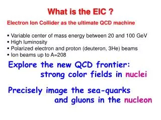
Innovative Magnet Design for EIC: Optimal Field Quality and High Gradient
160 likes | 176 Vues
Explore the design and fabrication of advanced IR magnets for EIC, focusing on conductor options, magnet layouts, and optimization strategies to meet accelerator and experimental requirements. Learn about cutting-edge magnet technologies and fabrication processes such as CosqCoils and Direct Wind.

Innovative Magnet Design for EIC: Optimal Field Quality and High Gradient
E N D
Presentation Transcript
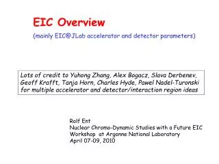
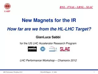
The IR Magnets for EIC Acknowledgements GianLuca Sabbi Lawrence Berkeley National Laboratory M. Anerella, J. Cozzolino, R. Palmer, B. Parker, S. Plate, J. Schmalzle, H. Witte, P. Wanderer (BNL) T. Michalski, P. Ghoshal, F. Lin, V. Morozov, R. Rajput-Ghoshal, R. Yoshida, M. Wiseman(JLAB) Y. Cai, Y. Noscokhov, M. Sullivan (SLAC)
Presentation Outline • EIC IR Magnet requirements • Conductor/Technology Options • IR layouts for eRHIC and JLEIC • IR Magnets Design for EIC • Downstream ion quads • Magnet length optimization • Field quality analysis • Helical tapered electron quads • Large aperture dipoles • High Gradient Quadrupole R&D • Summary eRHIC JLEIC
EIC IR Design Requirements • Experimental: • Acceptance of charged and neutral particles in the forward direction of the hadron beam • Limit background and detector damage from e-beam synchrotron radiation • Operate in a wide range of beam energy/current with good field quality • Integrate detector elements (e.g. spectrometers) in IR layout • Operate under high heat load from IP (cooling, radiation lifetime) • Accelerator: • Large focusing strengthfor small beam size at the IP and high luminosity • Compact designs and/or interleaved electron and ion magnets in order to minimize crossing angle and crab cavity system requirements • Control magnet fringe fields to minimize perturbations on adjacent beam optics
Conductor Options NbTi Nb3Sn • All present designs for both eRHIC and JLEIC IR magnets are based on NbTi • Compact Nb3Sn quadrupoles are being explored by the EIC R&D program
Magnet Design and Fabrication: CosqCoils • The cos(nq)coil layout with keystone Rutherford cablehas dominated accelerator applications to date due to its efficiency and field quality • This layout is compatible with both NbTi and Nb3Sn magnet technology • However, it requires complex tooling which is specific to each design
Magnet Design and Fabrication: Direct Wind An automated process providing flexibility in the winding pattern of NbTi coils without a need for dedicated tooling • Main steps in the coil fabrication process: • Support tube is placed on a rotating support and wrapped with epoxy substrate. • The conductor is epoxy coated and placed in the desired pattern by a winding head mounted on a gantry • Ultrasonic heating bonds the conductor to the substrate • After each layer is completed, gaps are filled with spacers (e.g. G10) and epoxy to provide a winding surface for next layer • A fiberglass wrap is wound under tension to compact the coil layers and provide radial support • Ahigh temperature cure completes the coil • Well suited for complex winding patterns, compactness, active shielding in a moderate field /force range • Successfully applied to special magnets for: HERA-II, BEPC-II and ILC IR, J-PARC and BTeV correction coils, Alpha anti-hydrogen trap
Magnet Design and Fabrication: Helical Coils • Basic concept: superposition of tilted solenoids to generate a dipole field • Windings can be further modulated to generate higher order multipoles and/or control the field in curved or tapered geometries • Flexible field generation concept with a variety of potential applications • Winding pattern can be implemented by Direct Wind or grooved formers Quadrupole design with helical coil Double Helix Dipole Canted Cosine Theta Meyer, NIM (1970)
IR Layouts and Selected Magnet Topics • Downstream ion quadrupoles: eRHIC (Q1ApF, Q1BpF, Q2pF) and JLEIC (iQDS1a/b, iQDS2) • Magnetic length optimization (JLEIC iQDS1a ) • Field quality estimates (JLEIC eQUS1/2/3, eQDS1/2/3) • Helical quadrupoles (eRHIC Q1eR, Q2eR) • Large aperture dipoles (eRHIC B0pF, B1pF) • eRHIC: 25 mrad crossing angle • JLEIC: 50 mrad crossing angle
Downstream Hadron Quadrupoles: eRHIC • Main design requirements and features: • Provide neutron cone acceptance of ± 4 mrad • Quads are tilted and shifted relative to the beam axis to minimize required aperture and maximize iron thickness on the electron beam side while avoiding a tapered coil geometry • Resulting coil radius is 56-131 mm and coil peak field 4.1-5.3 T: design is based on collared cos2q NbTi coil (1.9K may be required) • Q2eF is housed in a common yoke with Q1BpF (no gap available between hadron quads)
Downstream Hadron Quadrupoles: JLEIC 10 GeV/c electrons 200 GeV/c protons mrad • Main design requirements and features: • Provide neutron cone acceptance of ± 10 mrad • Clear bore up to 177 mm, add ~8 mm for coil radius • Design is based on collared cos2q NbTi coil: very large magnets but experience with CEBAF Hall C SHMS-Q2 • 50 mrad crossing angle allows more transverse space for shielding: no shift/tilt, separate electron magnets iQDS2
Magnet Length Optimization • Longitudinal space allocation is very tight: • Coil end geometry has to be optimized for winding the Rutherford cable • Spacers to control peak field and field quality make the coil end less compact • Include space for engineering features: leads, axial force support, cryostat • Estimate field quality and allocate space for correctors based on DA calculations • Option to increase operating gradient is limited by NbTi properties Example: iQDS1a (JLEIC) end field quality Baseline (compact) end Integrated b6: -43.3 units over 406.3 mm With additional spacer +17mm Integrated b6 is zero
Field Quality Analysis • Design challenges: • Operation over a large energy/field range • Proximity among beam lines: minimize coupling despite small radial space for shielding • Field errors to be considered: • Geometric: 2D and 3D (coil ends) including systematic, uncertainty and random • Iron saturation and conductor magnetization Example: JLEIC electron quads: 90mm bore, 600 mm length, 20-45 T/m, ~5 T coil field B[T] Random errors (1 sigma) for 100 mm block displacements Saturation effect on b6 (Rref=35 mm, ~2/3 Rbore) 2x16 independent variables Rref=35 mm 3.1 kA Saturated region
Helical Tapered Electron Quads • Main design requirements and features: • Electron magnets on the rear side need to pass synchrotron radiation (SR) without backscatter • Large bore limits the radial space for coil and iron, especially on the IP side • Based on helical tapered coils with Direct Wind • Developed for eRHIC but may also benefit JLEIC Q2eR coil model Shared Yoke B2(z) @ R=10 mm Test coil with Direct Wind Q2eR Q1BpR Fabricated by Direct Wind
Large Aperture Dipoles • Design requirements: very large bore and proximity/overlap with electron beam line • Two examples from eRHIC are shown, but design solutions are also applicable to JLEIC B0pF spectrometer: 1.3 T, 200 mm bore • Q0eF is nested in the bore of B0pf • Compensation dipole bucks B0pF. Iron shield cancels residual field and returns Q0eF flux • B1pF: 3.4 T, 270 mm • Field free channel in yoke for e beam
High Gradient Nb3Sn Quadrupole R&D • Nb3Sn technology is more complex but may offer significant advantages to EIC • Higher gradient shorter length smaller aperture iterate • A short model demonstrator is being developed as part of the EIC R&D effort • Design focus is on compact mechanical structure and reducing the fringe field Recent progress: 4 LARP HQ coils selected, QA’d and shipped to BNL; structure design is complete and procurements under way Structure design 6” mechanical model HQ5 HQ7 HQ8 HQ9
Summary • The EIC physics goals place demanding requirements on the Interaction Region layout and magnets • Significant variety of designs parameters and conditions across the IR • Large aperture, high field, proximity of beamlines, detector interface • A broad range of technologies are being explored to meet these challenges • Advanced configurations to fit into the available space and reduce coupling • Coil fabrication: combination of traditional approaches, recent advances from HEP colliders and special techniques for flexibility of conductor placement • Several examples which are representative of the main design challenges and proposed solutions were presented • Individual designs were developed for either eRHIC or JLEIC, but they are generally applicable to both colliders • Current designs are based on NbTi to minimize development time, cost and risk • A Nb3Sn quadrupole is under development to address specific EIC and could open the way to alternative layouts with improved performance