Download
1 / 18
190 likes | 404 Vues
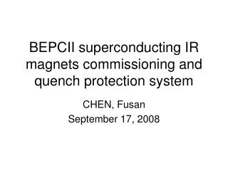
Superconducting IR Magnets. CHEN, Fusan May 11, 2007. Outline. Progress of the superconducting magnets and relevant systems. Power supplies and QPS were testified to be workable. Electronic test was done to the system. The magnets were cooled down to superconducting temperature.

E N D
Superconducting IR Magnets CHEN, Fusan May 11, 2007
Outline • Progress of the superconducting magnets and relevant systems. • Power supplies and QPS were testified to be workable. • Electronic test was done to the system. • The magnets were cooled down to superconducting temperature. • The whole system was assembled together. • The first commissioning of the magnets. • All coils were powered to 10~20% operating current. • Quench protection system was proved to be reliable. • Many problems were revealed with the valve boxes. • Schedule of the second commissioning and field measurement. • The valve boxes are rebuilt and the whole system is reassembled. • The second commissioning is in process. • Magnetic field measurement will be started after commissioning.
Progress of the PS and QPS • Power supplies met the requirements. • After months of tuning work, all power supplies were workable. • Power supply control system fulfilled the required functions. • Quench protection assembly reacted fast and correctly. • Reaction of the system was tested with dummy load. • Quench detection system was assembled. • Both hardware and software were ready.
Progress of the SC magnets • Electronic test before cooling. • The environment was not ideal. • Temperature: 25~28ºC Humidity: 95%~100% • Problems of the valve box. • The insulator failed in the hipot test at ~220VDC when the humidity was higher than 95%. • The temperature sensors were electrically connected to the current leads. • The hipot performance was concerned with the vacuum of the valve box.
Progress of the SC magnets • Monitoring the magnets during cooling. • To monitor the transformation from normal to superconducting of the coils, we powered the coils with low current (40mA) and monitored the voltage drops across the coils.
Progress of the SC magnets • Electronic test after cool-down. • Measured the resistance of gas cooled leads. • Hipot tests were repeated with all coils. • The grounding resistances of all coils were far less than requirement (20Mohm).
The first commissioning • More study on the hipot problem with BNL experts, George Ganetis and Wing Louie. • The grounding resistance of coils ranges from 2 to 8000 ohms. The resistance decreases when the valve box gets cold. • The resistance is non-linear and does not start to have current flowing until the voltage is greater then 1 Volt. • In all circuits the short is at or near the gas cooled lead. But the exact location of the short can not be found. • Possible causes of hipot failure. • All the electrical insulators used in the current leads have a creep path that is too small. • The G-10 insulators used on the top of the valve boxes can collect water.
Result of grounding resistance test * This table quotes from George’s report
The first commissioning • New problems of valve boxes • The current leads could not be cooled down. • The cold ends reached 20K with the flux controllers at max. • Reached 6K with the bypass valves at max. • AS, SCQ and SCB coils could not be powered more than 20% operating current, otherwise quenched. • The sensors could not indicate the temperature of the most critical points. • The inlet and outlet leads could not be cooled equally because they used common controller
The first commissioning • Some typical data and the diagnosis The signals monitored during the commissioning
Data of SCQ 162A 146A With the flow controller max, start the first ramping cycle Keeping the bypass valve open, start the second ramping cycle The SC bus quenches, but the normal region does not expand The SC bus does not quench at 162A 58A The SC bus cannot recover after opening the bypass valve Outlet Vt Inlet Vt Vt almost equals to Vc and Vs equals to zero for both inlet and outlet Outlet Vs Inlet Vs The SC bus recoveres after decreasing the current with the bypass valve opened
Data of AS 297A 245A 197A The normal region does not expand at 297A The inlet SC bus quench causes the jump of voltage signals while current increases to ~260A 148A It is important to analyze why the outlet does not quench even the Vt higher The Vt difference between the inlet and outlet shows the imbalance of the helium flow 98A 49A Outlet Vt Inlet Vt 9A Inlet Vs Outlet Vs
Learn more from SCQ 205A 195A 185A 175A 165A 146A The normal regions expand rapidly after 200A and the quench protection system is triggered. The normal regions do not expand under 200A Outlet Vt Inlet Vt
The second commissioning • The valve boxes are rebuilt and installed. • The quench detection circuit is set up and tested. • The warm temperature electronic test is performed. • The insulation of some temperature sensors on the current leads is not satisfying. • The power supplies are improved. • The ps control system is updated. • The interlock between systems is linked. • The cryogenic pipes are connected. • Now, the temperature reaches 60K.
The second commissioning • Next steps: (schedule is tight.) • Restore the quench protection software. (1 day) • Power the coils to 10~20% current. (5~6 days) • Tuning the parameters of quench detection system. • Check the ps and ps control system. • Check the quench protection assembly. • Configure the parameters of leads flux controller. • Power the coils to 50% current. (2 days) • Power the coils to 110% current. (2 days) • Tuning the power supplies. • Quench training if necessary. • The same powering procedure for the sync-rad mode. (4 days)
Schedule of field measurement • Joint field measurement. (37 days) • Instruments alignment, assembly, de-assembly, replacement (5 days). • Longitudinal field measurement with salamander. • Solenoid magnet off (1 day) & on (3 days). • Excitation curve measurement with stretch-line. • Solenoid magnet off (7 days) & on (7 days). • Rotating coil measurement (long & short coil). • Solenoid magnet off (4 days) & on (10 days).
Schedule of field measurement • Individual field measurement. (33 days) • Instruments alignment, assembly, de-assembly, replacement (5 days). • Excitation curve measurement with stretch-line (8 days for one magnet, totally 16 days). • Rotating coil measurement (12 days). • Long coil and short coil are used at the same time with different magnet. • Longitudinal field measurement with salamander (2 days).
Additional topic • The force and torque of SC magnet coils. • The special type magnets in IR work well. • Septum bending magnet: ISPB. • Dual aperture quadrupole: Q1a, Q1b. • Narrow quadrupole: Q2, Q3.