Download
1 / 33
340 likes | 549 Vues
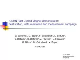
Fast Cycled superconducting Magnets (FCM) for PS2. WAMSDO, May 23 rd , 2008 Presented by L. Bottura on input from G. Kirby, M. Karppinen, L. Oberli, R. Maccaferri, C. Maglioni, V. Parma, D. Richter, G. de Rijk, L. Rossi, W. Scandale, L. Serio, D. Tommasini. Outline. Motivation

E N D
Fast Cycled superconducting Magnets (FCM) for PS2 WAMSDO, May 23rd, 2008 Presented by L. Bottura on input from G. Kirby, M. Karppinen, L. Oberli, R. Maccaferri, C. Maglioni, V. Parma, D. Richter, G. de Rijk, L. Rossi, W. Scandale, L. Serio, D. Tommasini
Outline • Motivation • Superconducting magnet design • R&D target and issues • Medium term plan • Conclusions and perspectives
Outline • Motivation • Superconducting magnet design • R&D target and issues • Medium term plan • Conclusions and perspectives
Courtesy of R. Garoby, CERN The LHC Accelerator Chain PS was built in 1959 SPS was commissioned in 1976
PS2 will be an accelerator with a length of ≈ 1.3 km Injection at 3.5 GeV Extraction at 50 GeV 200 dipoles Nominal field: 1.8 T Ramp-rate: 1.5 T/s Magnet mass: ≈15 tons 120 quadrupoles Nominal gradient 16 T/m Ramp-rate: 13 T/ms Magnet mass: ≈4.5 tons Average electric power ≈ 15 MW The magnets require ≈ 7.5 MW, i.e. about 50 % of the total consumption The location of the new PS2 dipole quadrupole Magnet design by courtesy of Th. Zickler, CERN PS2: Magnet Requirements Modest requirements
Outline • Motivation for the study • Superconducting magnet design • R&D target and issues • Medium term plan • Conclusions and perspectives
Design by courtesy of D. Tommasini and M. Karppinen, CERN Iron Dominated SC Dipole Bx [T] By [T] Bmod [T] A + 0.6 - 0.8 1.0 B + 0.4 + 0.2 0.4 C - 0.2 + 0.2 0.3 D 0.0 - 0.7 0.7 Bore field 1.8 T Warm iron yoke Cryostat Superconducting coil D C A B
Comparison of Dipole Designs Magnet length 3 m Number of magnets 200 Iron weight 10 tons Peak current @ 1.8 T 5300 A Current rise rate 4830 A/s Number of turns 2x10 Inductance 7 mH Peak voltage 34 V Magnet length 3 m Number of magnets 200 Iron weight 15 tons Peak current @ 1.8 T 5775 A Current rise rate 5260 A/s Number of turns 2x9 Inductance 6 mH Resistance 1.7 m RMS Current 3990 A Power consumption 27 kW Peak voltage 41 V
Design by courtesy of D. Tommasini, CERN Iron Dominated SC Quadrupole Bx [T] By [T] Bmod [T] A + 0.6 0.0 0.6 B + 0.6 0.0 0.6 C + 0.1 0.0 0.1 D + 0.1 0.0 0.1 Gradient 16 T/m Cryostat Superconducting coil D A C B
Comparison of quad designs Magnet length 1.75 m Number of magnets 120 Iron weight 2.8 tons Peak current @ 16 T/m 4600 A Current rise rate 3830 A/s Number of turns 4x6 Inductance 2.2 mH Peak voltage 8 V Magnet length 1.75 m Number of magnets 120 Iron weight 4.4 tons Peak current @ 16 T/m 1200 A Current rise rate 1000 A/s Number of turns 4x23 Inductance 35 mH Resistance 26.7 m RMS Current 830 A Power consumption 18 kW Peak voltage 67 V
NC magnets Dipoles: 30 MCHF Quadrupoles: 9 MCHF Testing: 1 MCHF Auxiliaries: 1.5 MCHF Power converters Total: 19.3 MCHF Cooling and ventilation Total: 1.1 MCHF Total cost: 61.9 MCHF SC magnets Dipoles: 21.3 MCHF Quadrupoles: 6.6 MCHF Testing: 3.2 MCHF Auxiliaries: 4 MCHF Cryogenics Plant + lines: 13.5 MCHF Building: 3.1 MCHF(1) Power converters Total: 15 MCHF Cooling and ventilation Total: 1.1 MCHF(2) Total cost: 67.8 MCHF Cost of NC PS2 by courtesy of M. Benedikt Cost comparison - investment (1) Scaled to 1/2 of estimate for the 15 kW plant (2) Assume the same as for NC magnets, benefiting from lower power requirement
Installed power of NC PS2 by courtesy of M. Benedikt Power requirements
NC magnets Energy: 14.6 MW * 6000 hrs/yr Energy cost(1): 3.8 MCHF/yr Total cost: 3.8 MCHF/yr SC magnets Energy: 7.6 MW * 6000 hrs/y Energy cost(1): 1.9 MCHF/yr Cryo maintenance: 0.3 MCHF/yr Total cost: 2.2 MCHF/yr bottom line Cost of NC PS2 by courtesy of M. Benedikt Cost comparison - operation Estimated ≈ 7 MW saving, half of the ≈ 15 MW projected power consumption of the PS2 complex, which corresponds to 1.6 MCHF/yr at the present cost of electricity (1) Assuming 40 CHF/MWh
Outline • Motivation • Superconducting magnet design • R&D target and issues • Medium term plan • Conclusions and perspectives
FCM = Bmax x (dB/dt)max=7 T2/s A Broader Perspective
FCM R&D Objectives • Build and test a demonstrator that: • Achieves PS2 nominal conditions (B=1.8 T, dB/dt = 1.5 T/s) and the =7 T2/s target (B=1.8 T, dB/dt ≈ 4 T/s) • Demonstrates the low-loss properties of the SC magnet option (1 W/m of magnet for the PS2 nominal conditions) • Address strand and cable R&D issues, relevant to both PS2 and SPS+ • Prototype of the of coil, cryostat, supports relevant for a PS2 • Various other side results, such as a demonstration of the cooling scheme, quench detectionandprotection, rampedfield qualityand itsmeasurement
Design by courtesy of M. Karppinen, CERN First Step: Short Dipole Model
Design by courtesy of M. Karppinen, CERN Critical Issues Identified to Date Warm iron Cryostat Winding pack and coil structure Superconducting strand and cable
Superconducting Strand and Cable • NbTi strand, modest critical current • Ic > 460 A @ 4.2 K and 2 T • Jc > 2500 A/mm2 @ 4.2 K and 5 T (below LHC standard) • Low-loss strand and cable • Deff < 3 m (≈ 3…4 m achieved on LHC strands) • 45 mJ/cm3 of NbTi for a +/- 1.5 T cycle • strand < 1 ms (≈ 0.1 ms achieved with resistive barriers on previous productions) • 9.5 mJ/cm3 of NbTi for a +/- 1.5 T cycle at 1 T/s • Cable n < 2 ms (corresponds to Ra ≈ 100 and Rc ≈ 10 m ) • 9.5 mJ/cm3 of NbTi for a +/- 1.5 T cycle at 1 T/s • Force-flow cooled cable • Stability advantage, robust against perturbations, for reliable operation, small He inventory, good voltage insulation properties, classical winding techniques
Nb-Ti Wire: Low Hysteresis Loss Design and prototyping work in progress on a strand with: Dstrand 0.6 mm Dfilament ≈ 2.5 m Cu/CuMn/NbTi ≈ 1.8 / ≈ 0.4 / 1
Force-Flow Cooled Cables • Low current (5…7 kA) • The first short models will be based on existing cables. A cable re-design is in progress • Larger hydraulic diameter for cooling efficiency • Co-wound copper strands for protection • Reduction of AC loss, depending on present status Internally cooled cable Prototype from VNIIKP Ra ≈ 75 … 200
inter-coil structure Coil Winding & Support Concept FEM ≈ 20 kN/m conductor former coil casing 4.5 K support post room temperature CL
Stiffened coil 77 K structure Through posts to the iron Horizontal straps and toblerone iron Design calculations and ideas by G. Kirby and M. Karppinen, CERN Coil Support Structure Make the coil self-supporting… Vertical load path: 0.8 tons/m Horizontal load path: 1.6 tons/m Composites and fibers to avoid eddy currents
Support feet Tensioned rods or straps Design by courtesy of C. Maglioni and V. Parma, CERN Cryostat and Supports • Conflicting requirements of mechanical rigidity vs. low heat input
Outline • Motivation for the study • Superconducting magnet design • R&D target and issues • Medium term plan • Conclusions and perspectives
Strand and cable design Conceptual design Demo dipole design Prototype strand Strand procurement Prototype cables Cable procurement Short model drawings and tools Short model parts (iron, former, structures, feet screen, cryostat) Coil winding Cryostating and assembly Short model tests Demo dipole drawings and tools Demo parts Coil winding Q1 Q1 Q1 Q2 Q2 Q2 Q3 Q3 Q3 Q4 Q4 Q4 Cryostating and assembly Demo test PS2 technical design Q2 Q3 Q4 2008 2009 2010 2011 Plan for FCM R&D
Outline • Motivation for the study • Superconducting magnet design • R&D target and issues • Medium term plan • Conclusions and perspectives
CNAO Carbon Therapy Center (Pavia, I) The rise of hadron therapy synchrotrons Conclusions and perspectives • This is a challenging bet: we are trying to displace normal conducting magnet technology from its proprietary domain. • We have to prove that our SC alternative is: • Equally reliable • Equally robust • More efficient This is a worthy effort, not only for the Beauty of Science !
Outline • Motivation for the study • Superconducting magnet design • R&D target and issues • Medium term plan • Conclusions • Additional information
Assumptions for cost analysis • SC magnet construction: • Iron yoke (warm): 6.6 CHF/kg • Superconducting coil: 250 CHF/kg • Cryostat: 25 kCHF/magnet • Magnet testing: 10 kCHF/magnet • SC auxiliaries: • Quench detection & protection: 1 MCHF total • Current leads and bus-bars: 3 MCHF total • Power converters costs are taken identical to previous analysis • Cooling and ventilation costs are assumed equal for NC and SC because of the reduced SC power requirement • Buildings cost for cryogenic plant are assumed to be reduced for the lower installed power • Operation: • Cryogenic operation is run by CERN (as power converters) • Electricity is quoted at 40 CHF/MWh
Is HTS an option ? • The use of HTS materials would affect: • Construction cost • Coil more expensive, cryostat simpler, smaller cryogenic installation (at best liquid nitrogen) • Operation • A larger margin to improve robustness • The cryogenic load can be removed at higher operating temperature, which requires lower installed power • Changes in the cost estimates for the SC PS2: • Investment cost reduced by 5 … 10 MCHF • Installed power reduced by 1 MW • Operation cost reduced by 0.25 MCHF/year Marginal gain with respect to previous figures (10 %) could be beneficial for the overall reliability
Nb-Ti Wire: Moderate Coupling Design time constant expected to be in the range of 0.5 to 1 ms (twist pitch of 6 mm)
2020 2008 2009 2010 2011 2012 2013 2014 2015 2016 2017 2018 2019 Magnet Projects and Related R&D Complete PS2 design PS2 construction FCM R&D HFM R&D NbTi IR upgrade Nb3Sn IR upgrade