Download

1 / 55
660 likes | 1.11k Vues
Superconducting Magnets for Accelerators. J. G. Weisend II National Superconducting Cyclotron Lab Michigan State University. Introduction. Superconducting Magnets are highly engineering devices material wire cable magnet Want to show examples

E N D
Superconducting Magnets for Accelerators J. G. Weisend II National Superconducting Cyclotron Lab Michigan State University
Introduction • Superconducting Magnets are highly engineering devices • material wire cable magnet • Want to show examples • Too much material for a 45 min talk • See backup slides & suggested readings for more information • Won’t really cover HTS or SCRF J. G. Weisend II
Acknowledgement • This talk includes many slides graciously provided by Luca Boturra of CERN
Nb-Ti Conventional iron electromagnets Graphics by courtesy of M.N. Wilson Why superconductivity anyhow ? • Abolish Ohm’s law ! • no power consumption (although need refrigeration power) • high current density • ampere turns are cheap, so don’t need iron (although often use it for shielding) • Consequences • lower running cost new commercial possibilities • energy savings • high current density smaller, lighter, cheaper magnets reduced capital cost • higher magnetic fields economically feasible new research possibilities
Abolish Ohm’s law - Super-conducting dipole Normal-conducting dipole Potential for saving 7 MW of the 15 MW estimatedtotal power consumption of an accelerator complex
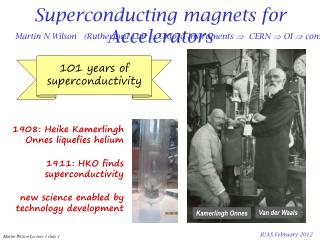
Superconductors Pre-history … thus the mercury at 4.2 K has entered a new state, which, owing to its particular electrical properties, can be called the state of superconductivity… H. Kamerlingh-Onnes (1911)
Cooper Pairs • Superconductor • paired electrons are bosons, a quasi particle in condensed state • zero resistance • Normal conductor • scattering of e- • finite resistance
Type I ( < 1/√2) Complete field exclusion B Pure metals BC ≈ 10-3…10-2 T B Type II ( > 1/√2) Partial field exclusion Lattice of fluxons Dirty materials: alloys intermetallic, ceramic BC ≈ 10…102 T Ginzburg, Landau, Abrikosov, Gor’kov, 1950…1957 Hey, what about field ? Raise field superconducting normal-conducting Cool down Meissner & Ochsenfeld, 1933
Graphics by courtesy of Superconductor Lab, Oslo Lattice of quantum flux lines Supercurrent Flux quantum 0= h/2e = 2.07 x 10⁻¹⁵ Wb Observation on Pb-4at% In magnetised by a field of 3000 Oe and decorated by Co particles Essmann & Träuble, 1967
Tc(K) Graphics by courtesy of M.N. Wilson Critical temperature and field The upper critical field BC2 and temperature TC of metallic superconductors are mutually related Both BC2 and TC are determined by the chemistry of the material HTS NOTE: of all the metallic superconductors, only NbTi is ductile. All other are brittle inter-metallic compounds
Hey, what about current ? • A current flowing in a magnetic field is subject to the Lorentz force that deviates the charge carriers: F = J x B • This translates into a motion of the fluxoids across the superconductor energy dissipation loss of superconductivity • To carry a significant current we need to lock the fluxoids so to resist the Lorentz force. For this we mess-up the material and create pinning centers that exert a pinning force FP
Graphics by courtesy of Applied Superconductivity Center at NHMFL Pinning mechanisms Grain boundaries in inter-metallic compounds Precipitates in alloys grain Microstructure of Nb-Ti Microstructure of Nb3Sn Today we are engineering the structure of superconductors at a microscopic scale via heat treating, alloying and cold work
The maximum current that can be carried by the superconductor is the current at which: |J x B| = FP The above expression defines a critical surface: JC(B,T,…) = FP / B Jc [A/mm2] T=1.9 K T=4.2 K B = 5 [T] 100,000 10,000 1,000 B [T] 100 T [K] 5 5 10 10 15 Critical surface of a LHC NbTi wire Jc(B,T,…) Jc (5 T, 4.2 K) ≈ 3000 A/mm2
Practical Superconductor Facts • Superconductor s are relatively poor conductors when normal • Superconductors do have resistive losses when the current is varied • Superconductors can’t generally be used as a bulk material. They are divided into filaments (tens of mm in DIA) housed in a good conductor matrix. This: • Prevents flux jumping and heating • Increases stability
Engineering current density • All wires, tapes and cables contain additional components: • Left-overs from the precursors of the SC formation • Barriers, texturing and buffering layers • Low resistance matrices • The SC material fraction is hence always < 1: = ASC / Atotal • To compare materials on the same basis, we use an engineering current density: JE = JC x
extrusion cold drawing heat treatments 1 mm Graphics by courtesy of Applied Superconductivity Center at NHMFL Nb-Ti manufacturing route NbTi billet IC(5 T, 4.2 K) ≈ 1 kA NbTi is a ductile alloy that can sustain large deformations LHC wire
Graphics by courtesy of Applied Superconductivity Center at NHMFL Nb3Sn manufacturing routes Nb3Sn is brittle and cannot be drawn in final form. The precursors are drawn and only later the wire is heat-treated to ≈650 C, to form the Nb3Sn phase IC(12 T, 4.2 K) ≈ 1.5 kA
Multifilamentary wires have current carrying capability of 100… 1000 A Insulated with varnish or glass-braids they can be used to make all kind of small size magnets Large size magnets (e.g. LHC dipoles) require invariably large operating currents (10 to 100 kA) to: Decrease inductance, Lower the operating voltage, Ease the magnet protection Rutherford cables are ideally suited for this task JE ≈ 500 A/mm2 Practical conductors: high JE LHC cable prototype
Super-stabilized conductor, a superconducting cable (e.g. Rutherford) backed by a large amount of good normal conductor (e.g. Al) Internally-cooled conductor, e.g. Cable-In-Conduit Conductor (CICC), a rope of wires inserted in a robust conduit that provides a channel for cooling JE ≈ 50 A/mm2 Practical conductors: low JE
IC = JC x ASC Critical line and magnet load lines e.g. a 5 T magnet design NbTi critical surface NbTi critical current IC(B) 7 6 5 4 5 T Bore field quench ! Current density kA/mm2 3 2 Peak field 1 2 2 4 4 Temperature K 6 6 8 8 10 Field T 10 12 14 we expect the magnet to go resistive i.e. to 'quench', where the peak field load line crosses the critical current line
Temperature rise may be caused by sudden mechanical energy release AC losses Resistive heat at joints Beams, neutrons, etc. We should allow temperature headroom for all foreseeable and unforeseeable events, i.e. a temperature margin: T = TCS-Top Temperature margin 5 T NbTi critical current Ic(T) 6 T Iop T≈1.5 K Top TCS
Operating margins • Practical operation always requires margins: • Critical current margin: Iop/IQ ≈ 50 % • Critical field margin: Bop/BQ ≈ 75 % • Margin along the loadline: Iop/Imax ≈ 85 % • Temperature margin: TCS - Top ≈ 1…2 K • The margin needed depends on the design and operating conditions (see later) Current quench IQ Loadline quench Imax Field quench BQ Temperature quench TCS
Cooling of SuperconductorsVarious Possibilities Exist • Indirect (adiabatic magnets) • contact to a heat sink through conduction (cryoplant, cryocooler) • in practice no cooling on the time scale of interest for stability and quench • bath cooling (pool boiling magnets) • pool of liquid cryogen at atmospheric pressure and saturation temperature (e.g. helium at 4.2 K) • boiling heat transfer • force-flow cooling • supercritical or two-phase flow, warm or cold circulation • superfluid cooling • stagnant bath, heat removal through counter-flow heat exchange
forced-flow sub-cooled superfluid pool-boiling Helium as a coolant
Cryogenic Refrigeration • Cooling for superconducting magnets is well within the state of the art • Many commercial options exist (either off the shelf or custom) • The cryogenic system is best designed along with the magnet system as opposed to added on later
Cryogenic RefrigerationExamples Helium Refrigerator Coldbox (CTI400) 1200 W at 4.5 K Cryocooler: 0.1 W @ 4 K
Stability of Superconducting Magnets • When a s/c magnet undergoes a temperature rise, there are 2 possibilities: • It can cool back down and remain superconducting • It can warm up above Tc and “quench” (become normally conducting) • Which occurs depends on the amount of heat generation and cooling
A prototype temperature transient …effect of heat conduction and cooling… heat pulse… generation>cooling unstable generation<cooling stable
Perturbation spectrum • mechanical events • wire motion under Lorentz force, micro-slips • winding deformations • failures (at insulation bonding, material yeld) • electromagnetic events • flux-jumps (important for large filaments, old story !) • AC loss (most magnet types) • current sharing in cables through distribution/redistribution • thermal events • current leads, instrumentation wires • heat leaks through thermal insulation, degraded cooling • nuclear events • particle showers in particle accelerator magnets • neutron flux in fusion experiments
T < Tcs Tcs < T < Tc curent sharing T > Tc quenched TCS TC Current sharing stabilizer stabilizer superconductor superconductor IC Iop Top T
Stability of Superconducting Magnets • Fully cryostable: magnet will recover regardless of size of normal zone ( disturbance) May be true of large detector magnets e.g BaBar detector or MRI magnets • Partially cryostable: magnet will recover if normal is not too big – more typical of accelerator magnets
Criteria for Fully Cryostable Magnets • Stekly Criteria – most conservative, doesn’t account for end cooling • < magnet is stable • Equal area theorem • Takes into account the cooling of the conductor via conduction at the ends • Can be expressed as a graphical solution comparing the areas under the cooling and heating curves ( see references )
Quench Detection & Protection • Superconducting magnets store large amounts of energy either individually (20 MJ for the Babar detector magnet) or connected in series (10’s of GJ) • If all the energy is deposited in a small volume, bad things happen!
Quench Detection & Protection • The goal is to rapidly and accurately detect the quench and safely dispose of the energy • Evenly throughout the magnet • In an external dump resistor • In a coupled secondary • In magnet strings, bypass the energy of the other s/c magnets away from the quenching one • Remember it’s the stored energy in the magnet(s) not the power supply that’s problem
Detecting Quenches • Can’t just measure voltage directly as magnet ramping causes voltage and give a false signal • The general approach is to subdivide the magnet with voltage taps and build a bridge circuit that cancels out voltage due to ramping • Redundant QD systems are necessary • Other measurements such as temperature, helium level or vacuum level might be used to look for precursors to trouble but take care not to “over interlock the magnet”
S L Rdump Rquench normal operation quench B.J. Maddock, G.B. James, Proc. Inst. Electr. Eng., 115, 543, 1968 Strategy: energy dump • the magnetic energy is extracted from the magnet and dissipated in an external resistor: • the integral of the current: • can be made small by: • fast detection • fast dump (large Rdump)
the quench is spread actively by firing heaters embedded in the winding pack, in close vicinity to the conductor heaters are mandatory in: high performance, aggressive, cost-effective and highly optimized magnet designs… …when you are really desperate advantages: homogeneous spread of the magnetic energy within the winding pack disadvantages: active high voltages at the heater Doesn’t work well with highly stable magnets Strategy: heaters heater winding
MN M1 M2 M3 Magnet strings • magnet strings (e.g. accelerator magnets, fusion magnetic systems) have exceedingly large stored energy (10’s of GJ): • energy dump takes very long time (10…100 s) • the magnet string is subdivided and each magnet is by-passed by a diode (or thyristor) • the diode acts as a shunt during the discharge
Bnominal 8.3 (T) current 11850 (A) stored energy 1 (MJ) cold mass 35 (tonnes) LHC dipole
Superconducting dipole magnet coil J +J J +J Ideal current distribution that generates a perfect dipole Practical approximation of the ideal distribution using Rutherford cables
Twin coil principle Combine two magnets in one Save volume, material, cost
LHC dipole coils B B
Coil winding Cable insulation 10 m precision ! Stored coils B B Coil winding machine
Ends Layer jump Inner layer Ends, transitions, and any deviation from the regular structure are the most delicate part of the magnet
Collaring and yoking 85 tons/m F 175 tons/m yoking collaring
Vacuum enclosure Low conduction foot Thermal screens Cryostat
Example 2BaBar Detector S/C Solenoid • Provided background field for particle identification for the BaBar detector at SLAC • Physics requirements dictated a relatively thin solenoid J. G. Weisend II
Properties of BaBar Solenoid • Field: 1.5 Tesla • Stored Energy: 27 MJ • Operating Current: 4596A • Tc= 8.3K • Operating Temp: 4.5K • Total Heat Load at 4.5K: 225liquid-liters/hr • Cryogenics: indirectly cooled using the force flow technique where the liquid He is circulated in cooling pipes welded to the outside diameter of the support tube • Uses NbTi highly stabilized in a pure Al conductor