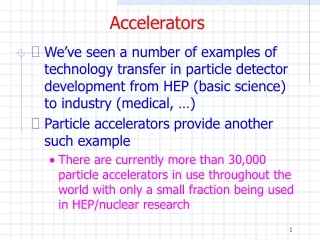
Overview of Room-Temperature Magnet Technology for Particle Accelerators
This presentation provides a comprehensive overview of magnet technology specifically for particle accelerators, focusing exclusively on room-temperature electro-magnets. Key topics include the design and construction of dipole, quadrupole, and sextupole magnets, alongside discussions of magneto-statics principles and the introduction of ferromagnetic materials. If time permits, the session may delve into magnetic measurements and construction techniques. Notably excluded from the discussion are permanent magnet and superconducting technologies.

Overview of Room-Temperature Magnet Technology for Particle Accelerators
E N D
Presentation Transcript
Conventional Magnets for Accelerators Neil Marks, ASTeC, Cockcroft Institute, Daresbury, Warrington WA4 4AD, neil.marks@stfc.ac.uk Tel: (44) (0)1925 603191 Fax: (44) (0)1925 603192
Philosophy • Present a overview of magnet technology as used in particle accelerators, concerned only with room-temperature electro-magnets. • The special cases of a.c. and pulsed magnets (inc something on magnetic materials); • If time allows we shall also look at magnmetic measurements and construction techniques. • Not covered: • i) permanent magnet technology; • ii) super-conducting technology.
DC Magnets-design and construction. a) Introduction: Dipole magnets; Quadrupole magnets; Sextupole magnets; ‘Higher order’ magnets. b) Magneto-statics in free space (no ferromagnetic materials or currents): Maxwell's 2 magneto-static equations; Solutions in two dimensions with scalar potential (no currents); Cylindrical harmonic in two dimensions (trigonometric formulation); Field lines and potential for dipole, quadrupole, sextupole; Significance of vector potential in 2D. Contents – first phase.
c) Introduce ferromagnetic poles: Ideal pole shapes for dipole, quad and sextupole; Field harmonics-symmetry constraints and significance; 'Forbidden' harmonics resulting from assembly asymmetries. d) Cylindrical harmonics in the complex formulation. e) The introduction of currents and the magnetic circuit: Ampere-turns in dipole, quad and sextupole. Coil economic optimisation-capital/running costs. The magnetic circuit-steel requirements-permeability and coercivity. Backleg and coil geometry- 'C', 'H' and 'window frame' designs. Contents (cont.)
f) Magnet design and f.e.a. software. FEA techniques - Modern codes- OPERA 2D; TOSCA. Judgement of magnet suitability in design. Classical solution to end and side geometries – the Rogowsky roll-off. Magnet ends-computation and design. Contents (cont.)
But first – nomenclature! Magnetic Field: (the magneto-motive force produced by electric currents) symbol is H (as a vector); units are Amps/metre in S.I units (Oersteds in cgs); Magnetic Induction or Flux Density: (the density of magnetic flux driven through a medium by the magnetic field) symbol is B (as a vector); units are Tesla (Webers/m2 in mks, Gauss in cgs); Note: induction is frequently referred to as "Magnetic Field". Permeability of free space: symbol is µ0 ; units are Henries/metre; Permeability (abbreviation of relative permeability): symbol is µ; the quantity is dimensionless;
Magnets - introduction • Dipoles to bend the beam: Quadrupoles to focus it: Sextupoles to correct chromaticity: We shall establish a formal approach to describing these magnets.
Magnets - dipoles To bend the beam uniformly, dipoles need to produce a field that is constant across the aperture. But at the ends they can be either: Parallel ended dipole. Sector dipole They have different focusing effect on the beam; (their curved nature is to save material and has no effect on beam focusing).
B B beam Dipole end focusing Sector dipoles focus horizontally : The end field in a parallel ended dipole focuses vertically : Off the vertical centre line, the field component normal to the beam direction produces a vertical focusing force.
Magnets - quadrupoles Quadrupoles produce a linear field variation across the beam. Field is zero at the ‘magnetic centre’ so that ‘on-axis’ beam is not bent. Note: beam that is radially focused is vertically defocused. These are ‘upright’ quadrupoles.
‘Skew’ Quadrupoles. Beam that has radial displacement (but not vertical) is deflected vertically; horizontally centred beam with vertical displacement is deflected radially; so skew quadrupoles couple horizontal and vertical transverse oscillations.
By x Magnets - sextupoles In a sextupole, the field varies as the square of the displacement. • off-momentum particles are incorrectly focused in quadrupoles (eg, high momentum particles with greater rigidity are under-focused), so transverse oscillation frequencies are modified - chromaticity; • but off momentum particles circulate with a radial displacement (high momentum particles at larger x); • so positive sextupole field corrects this effect – can reduce chromaticity to 0.
Magnets – ‘higher orders’. • eg – Octupoles: • Effect? • By x3 • Octupole field induces ‘Landau damping’ : • introduces tune-spread as a function of oscillation amplitude; • de-coheres the oscillations; • reduces coupling.
No currents, no steel - Maxwell’s static equations in free space: • .B = 0 ; • H = j ; In the absence of currents: j = 0. Then we can put: B = - So that: 2 = 0 (Laplace's equation). Taking the two dimensional case (ie constant in the z direction) and solving for cylindrical coordinates (r,): = (E+F )(G+H ln r) + n=1 (Jn r n cos n+Kn r n sin n +Ln r -n cos n + Mn r -n sin n )
In practical situations: • The scalar potential simplifies to: • = n (Jn r n cos n +Kn r n sin n), • with n integral and Jn,Kn a function of geometry. Giving components of flux density: Br = - n (n Jn r n-1 cos n +nKn r n-1 sin n) B = - n (-n Jn r n-1 sin n +nKn r n-1 cos n)
Physical significance • This is an infinite series of cylindrical harmonics; they define the allowed distributions of B in 2 dimensions in the absence of currents within the domain of (r,). • Distributions not given by above are not physically realisable. • Coefficients Jn, Kn are determined by geometry (remote iron boundaries and current sources).
In Cartesian Coordinates • To obtain these equations in Cartesian coordinates, expand the equations for f and differentiate to obtain flux densities; • cos 2q = cos2q – sin2q; cos 3q = cos3q – 3cosq sin2q; • sin2q = 2 sinq cosq; sin3q = 3sin2q – sin3q; • cos 4q = cos4q + sin4q – 6 cos2q sin2q; • sin 4q = 4 sinq cos3q – 4 sin3q cosq; • etc (messy!); • x = r cos q; y = r sin q; • and Bx = - f/x; By = - f/y
n = 1? Dipole field! • Cylindrical:Cartesian: • Br = J1 cos + K1 sin ; Bx = J1 • B = -J1 sin + K1 cos ; By = K1 • =J1 r cos +K1 r sin . =J1 x +K1 y So, J1 = 0 gives vertical dipole field: K1 =0 gives horizontal dipole field.
n = 2? Quadrupole field ! • Cylindrical: Cartesian: • Br = 2 J2 r cos 2 +2K2 r sin 2; Bx = 2 (J2 x +K2 y) • B = -2J2 r sin 2 +2K2 r cos 2; By = 2 (-J2 y +K2 x) • = J2 r 2 cos 2 +K2 r 2 sin 2; = J2 (x2 - y2)+2K2 xy J2 = 0 gives 'normal' or ‘right’ quadrupole field. Line of constant scalar potential K2 = 0 gives 'skew' quad fields (above rotated by /4). Lines of flux density
-C +C +C -C -C +C n = 3 ? Sextupole field ! • Cylindrical; Cartesian: • Br = 3 J3r2 cos 3 +3K3r2 sin 3; Bx = 3J3 (x2-y2)+2K3yx • B= -3J3 r2 sin 3+3K3 r2 cos 3; By = 3-2 J3 xy + K3(x2-y2) • = J3 r3 cos 3 +K3 r3 sin 3; = J3 (x3-3y2x)+K3(3yx2-y3) -C J3 = 0 giving 'normal' or ‘right’ sextupole field. +C +C Line of constant scalar potential -C -C Lines of flux density +C
By x Summary; variation of By on x axis • Dipole; constant field: • Quad; linear variation: • Sextupole: quadratic variation: By x By x
Alternative notification (Most lattice codes) magnet strengths are specified by the value of kn; (normalised to the beam rigidity); order n of k is different to the 'standard' notation: dipole is n = 0; quad is n = 1; etc. k has units: k0 (dipole) m-1; k1 (quadrupole) m-2; etc.
Significance of vector potential in 2D. We have: B = curl A (A is vector potential); and div A = 0 Expanding: B = curl A = (Az/ y - Ay/ z) i + (Ax/ z - Az/ x) j + (Ay/ x - Ax/ y) k; where i, j, k, and unit vectors in x, y, z. In 2 dimensions Bz = 0; / z = 0; So Ax = Ay = 0; and B= (Az/ y ) i - (Az/ x) j A is in the z direction, normal to the 2 D problem. Note: div B = 2Az/ x y - 2Az/ x y = 0;
B A1 A2 F Total flux between two points DA In a two dimensional problem the magnetic flux between two points is proportional to the difference between the vector potentials at those points. F (A2 - A1) Proof on next slide.
dS B A l ds z y (x1, y1) (x2, y2) x Proof. Consider a rectangular closed path, length l in z direction at (x1,y1) and (x2,y2); apply Stokes’ theorem: F = B.dS= ( curl A).dS= A.ds But A is exclusively in the z direction, and is constant in this direction. So: A.ds = l { A(x1,y1) - A(x2,y2)}; F = l { A(x1,y1) - A(x2,y2)};
Introducing Iron Yokes • What is the ideal pole shape? • Flux is normal to a ferromagnetic surface with infinite : curl H = 0 therefore H.ds = 0; in steel H = 0; therefore parallel H air = 0 therefore B is normal to surface. = = 1 • Flux is normal to lines of scalar potential, (B = - ); • So the lines of scalar potential are the ideal pole shapes! (but these are infinitely long!)
R Equations for the ideal pole • Equations for Ideal (infinite) poles; • (Jn = 0) for normal (ie not skew) fields: • Dipole: • y= g/2; • (g is interpole gap). • Quadrupole: • xy= R2/2; • Sextupole: • 3x2y - y3 = R3;
Combined function (c.f.) magnets • 'Combined Function Magnets' - often dipole and quadrupole field combined (but see next-but-one slide): • A quadrupole magnet with • physical centre shifted from • magnetic centre. • Characterised by 'field index' n, • +ve or -ve depending • on direction of gradient; • do not confuse with harmonic n! is radius of curvature of the beam; Bo is central dipole field
Combined function geometry • Combined function (dipole & quadrupole) magnet: • beam is at physical centre • flux density at beam = B0; • gradient at beam = B/x; • magnetic centre is at B = 0. • separation magnetic to physical centre = X0 x’ x X0 magnetic centre, x’ = 0 physical centre x = 0
Other combined function magnets. • dipole, quadrupole and sextupole; • dipole & sextupole (for chromaticity control); • dipole, skew quad, sextupole, octupole ( at DL) Other combinations: Generated by • pole shapes given by sum of correct scalar potentials • - amplitudes built into pole geometry – not variable. • multiple coils mounted on the yoke • - amplitudes independently varied by coil currents.
The Practical Pole • Practically, poles are finite, introducing errors; • these appear as higher harmonics which degrade the field distribution. • However, the iron geometries have certain symmetries that restrict the nature of these errors. Dipole: Quadrupole:
Possible symmetries • Lines of symmetry: • Dipole: Quad • Pole orientation y = 0; x = 0; y = 0 • determines whether pole • is normal or skew. • Additional symmetry x = 0; y = x • imposed by pole edges. • The additional constraints imposed by the symmetrical pole edges limits the values of n that have non zero coefficients
+ + + - Dipole symmetries Type Symmetry Constraint Pole orientation () = -(-) all Jn = 0; Pole edges () = ( -) Kn non-zero only for: n = 1, 3, 5, etc; So, for a fully symmetric dipole, only 6, 10, 14 etc pole errors can be present.
Quadrupole symmetries Type Symmetry Constraint Pole orientation () = -( -) All Jn = 0; () = -( -) Kn = 0 all odd n; Pole edges () = (/2 -) Kn non-zero only for: n = 2, 6, 10, etc; So, a fully symmetric quadrupole, only 12, 20, 28 etc pole errors can be present.
Sextupole symmetries Type Symmetry Constraint Pole orientation () = -( -) All Jn = 0; () = -(2/3 - ) Kn = 0 for all n () = -(4/3 - )not multiples of 3; Pole edges () = (/3 - ) Kn non-zero only for: n = 3, 9, 15, etc. So, a fully symmetric sextupole, only 18, 30, 42 etc pole errors can be present.
Summary - ‘Allowed’ Harmonics • Summary of ‘allowed harmonics’ in fully symmetric magnets:
Asymmetries generating harmonics (i) • Two sources of asymmetry generate ‘forbidden’ harmonics: • i) magnetic asymmetries - significant at low permeability: eg, C core dipolenot completely symmetrical about pole centre, but negligible effect with high permeability. Generates n = 2,4,6, etc.
n = 3, 6, 9, etc. Asymmetries generating harmonics (ii) • ii) asymmetries due to small manufacturing errors in dipoles: n = 2, 4, 6 etc.
n = 3; Asymmetries generating harmonics (iii) • ii) asymmetries due to small manufacturing errors in quadrupoles: n = 4 - ve n = 2 (skew) n = 3; n = 4 + ve These errors are bigger than the finite type, can seriously affect machine behaviour and must be controlled.
Complex formulation • Object: • a reminder of basic complex relationships; • introduce the function of the complex variable; • examine harmonic symmetries using complex notation; • set the scene for ‘conformal transformations’ (briefly).
Bibliography • The seminal paper on calculation of harmonics generated by assembly errors (using the complex formulation): • ‘First Order Perturbation Effects in iron-Dominated 2D Symmetrical Multipoles; • K. Halbach; • N.I.M., 74 (1969) 147 – 164. • General Introductions: • ‘Complex Variable Methods in Science and Technology’ • J.Cunningham; • Van Nostrand 1965. • ‘Conformal Transformations in Electrical Engineering’, • W.J.Gibbs, • Chapman & Hall 1958
y r q x The Complex Variable the complex variable z = x +iy; conjugate z*= x – iy also expressed as z = r (cos q + i sin q); and z = r exp(iq); ‘modulus’ mod z = r = √(x2+y2); ‘argument’ arg z = q = tan-1(y/x). Note de Moivre’s theorem: (cos q +i sin q)n = (cos nq +i sin nq). The Z plane:
Functions of a complex variable. Written as f(z); and f(z) = u(x,y) + i v(x,y); u (x,y) = Re f(z); v (x,y) = Im f(z); For example f(z) = z2 – 2z; then: f(z) = x2 – y2 + 2 ixy – 2x -2 iy; so: u(x,y) = x2 – y2 - 2x; v(x,y) = 2(xy – y); We shall be considering functions f(z) which are ‘continuous’, regular’ and ‘differentiable’. This places severe restrictions on the class of the two functions u(x,y) and v(x,y).
Consequences of ‘regularity’. The differential of a function f(z) is given by: Lt zz0{(f(z) – f(z0))/(z – z0)}; To be ‘regular’ (‘differentiable’) the value must not depend on the direction z approaches z0: can be along the real axis or the imaginary axis! This results in the Cauchy-Riemann equations for u and v: u / x = v / y ; v/ x = - u/ y. For the example above: f(z) = z2 – 2z, u/ x = 2 x – 2; v/ y = 2 x – 2; v/ x = 2 y; u/ y = - 2 y.
Cauchy-Riemann and Laplace. Functions that satisfy Cauchy-Riemann equations also satisfy Laplace’s equation in two dimensions: For u: u / x = v / y; differentiate w.r.t. x: 2u / x2 = 2v / x y = /y ( v/ x ); but: v/ x = - u/ y so: 2u / x2 = /y(- u/y) = - 2u / y2; and 2u / x2 + 2u/ y2 = 0; (Laplace’s equation in 2D). Similarly for v:v / y = u / x; differentiate w.r.t. y: 2v / y2 = 2u / x y ; = - 2 v/ x2 so: 2v / x2 + 2v/ y2 = 0; (Laplace’s equation in 2D)
Application to potentials. Note that from Cauchy-Riemann: (u / x).(v / x ) + (v / y).(u / y) = 0; So the lines u = constant, v = constant, are orthogonal; In 2D ‘Laplace’ problems (electro-statics, magneto-statics, fluid flow), u and v can represent the potential function and the flow function (stream-lines). So, we can set up a complex potential with real and imaginary parts: i) the lines of flux (ie contours of Az); ii) lines of scalar potential. Note – it does not matter which we make the real and imaginary parts, as long as we are consistent.
Field and potential equations We define the complex potential F: F = Az + if; the complex flux density: B = Bx + iBy Now: F/ x = Az/ x + i f/ x; = - By - i Bx; F/(i y) = (1/i) Az/ y + f/ y; = -i Bx – By; So we can write: B*= i dF/ dz; (z = x +iy)
Allowed harmonics The harmonic expansion now becomes: F = n=1Jn zn ; where Jn are complex coefficients giving both upright and skew component amplitudes; For a symmetric 2N pole magnet: Fn= Jnexp(ipn/N) all integer n; so: Fn = 0 or ± i unless n = N(2m +1), m = 0,1,2,..
Introduction of currents Now for j 0 H = j ; To expand, use Stoke’s Theorum: for any vector V and a closed curve s : V.ds =curl V.dS Apply this to: curl H =j ; then in a magnetic circuit: H.ds = N I; N I (Ampere-turns) is total current cutting S