Download
1 / 110
1.12k likes | 1.25k Vues
Explore conventional magnets and super-conducting magnets for accelerators. Learn design, construction, and software usage for magnet optimization. Study magnetic field manipulations and coil economics. Gain insights into magneto-statics, dipole, quadrupole, sextupole magnets, and higher-order magnets.

E N D
Magnets for Accelerators – conventional and (some) super-conducting. Neil Marks, ASTeC, Cockcroft Institute, Daresbury, Warrington WA4 4AD, neil.marks@stfc.ac.uk
Course Philosophy • Provide an introduction to magnet technology in particle accelerators for: • room-temperature,static (d.c.) electro-magnets, and • an initial overview of the low-temperature super-conducting (LTS) magnets, concentrating on electro-magnetic issues. • To introduce students to the use of the FEA code OPERA 2D – to enable on-going design work in the next 6 weeks.
DC Magnets-design and construction: a) Introduction: Nomenclature; Dipole, quadrupole and sextupole magnets; ‘Higher order’ magnets. b) Magneto-statics in free space (no ferromagnetic materials or currents): Maxwell's 2 magneto-static equations; Solutions in two dimensions with scalar potential (no currents); Cylindrical harmonic in two dimensions (trigonometric formulation); Field lines and potential for dipole, quadrupole, sextupole; Significance of vector potential in 2D. Contents – lectures 1&2.
c) Adding ferromagnetic poles: Ideal pole shapes for dipole, quad and sextupole; Field harmonics-symmetry constraints and significance; d) The addition of currents: Ampere-turns in dipole, quad and sextupole. Coil economic optimisation-capital/running costs. e) The magnetic circuit: Steel requirements-permeability and coercivity. Backleg and coil geometry- 'C', 'H' and 'window frame' designs. Classical solution to end and side geometries – the Rogowsky roll-off. Contents (cont.)
f) An introduction to super-conducting magnets: Basic concepts; Materials for and design of coils; External cold steel. g) Magnet design using f.e.a. software: FEA techniques - Modern codes- OPERA 2D; OPERA 3D. Judgement of magnet suitability in design. Magnet ends-computation and design. h) Some examples of recent magnet engineering; i) Appendix relating specifically to super-conductivity: Provides more information on some issues; Further information needed for the tutorial. Contents (cont.)
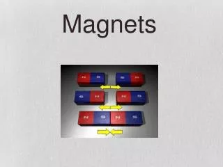
Nomenclature. • Magnetic Field: (the magneto-motive force produced by electric currents) • symbol is H (as a vector); • units are Amps/metre in S.I units (Oersteds in cgs); • Magnetic Induction or Flux Density: (the density of magnetic flux driven through a medium by the magnetic field) • symbol is B (as a vector); • units are Tesla (Webers/m2 in mks, Gauss in cgs); • Note: induction is frequently referred to as "Magnetic Field". • Permeability of free space: • symbol is µ0 ; • units are Henries/metre; • Permeability (abbreviation of relative permeability): • symbol is µ; • the quantity is dimensionless;
Magnet types • Dipoles to bend the beam: • Quadrupoles to focus it: • Sextupoles to correct chromaticity: • We shall establish a formal approach to describing these magnets.
Magnets - dipoles • To bend the beam uniformly, dipoles need to produce a field that is constant across the aperture. • But at the ends they can be either: • Parallel ended dipole. • Sector dipole • They have different focusing effect on the beam; • (their curved nature is to save material and has no effect on beam focusing).
B • B • beam Dipole end focusing • Sector dipoles focus horizontally : • The end field in a parallel ended dipole focuses vertically : • Off the vertical centre line, the field component normal to the beam direction produces a vertical focusing force.
Magnets - quadrupoles • Quadrupoles produce a linear field variation across the beam. • Field is zero at the ‘magnetic centre’ • so that ‘on-axis’ beam is not bent. • Note: beam that is radially • focused is vertically • defocused. • These are ‘upright’ quadrupoles.
‘Skew’ Quadrupoles. • Beam that has radial displacement (but not vertical) is deflected vertically; • horizontally centred beam with vertical displacement is deflected radially; • so skew quadrupoles couple horizontal and vertical transverse oscillations.
By • x Magnets - sextupoles • In a sextupole, the field varies as the square of the displacement. • off-momentum particles are incorrectly focused in quadrupoles (eg, high momentum particles with greater rigidity are under-focused), so transverse oscillation frequencies are modified - chromaticity; • but off momentum particles circulate with a radial displacement (high momentum particles at larger x); • so positive sextupole field corrects this effect – can reduce chromaticity to 0.
Magnets – ‘higher orders’. • eg – Octupoles: • Effect? • By x3 • Octupole field induces ‘Landau damping’ : • introduces tune-spread as a function of oscillation amplitude; • de-coheres the oscillations; • reduces coupling.
No currents, no steel - Maxwell’s static equations in free space: • .B = 0 ; • H = j ; • In the absence of currents: j = 0. • Then we can put: B = - • So that: 2 = 0 (Laplace's equation). • Taking the two dimensional case (ie constant in the z direction) and solving for polar coordinates (r,): • = (E+F )(G+H ln r) + n=1 (Jn r n cos n+Kn r n sin n • +Ln r -n cos n + Mn r -n sin n )
In practical situations: • The scalar potential simplifies to: • = n (Jn r n cos n +Kn r n sin n), • with n integral and Jn,Kn a function of geometry. • Giving components of flux density: • Br = - n (n Jn r n-1 cos n +nKn r n-1 sin n) • B = - n (-n Jn r n-1 sin n +nKn r n-1 cos n)
Physical significance • This is an infinite series of cylindrical harmonics; they define the allowed distributions of B in 2 dimensions in the absence of currents within the domain of (r,). • Distributions not given by above are not physically realisable. • Coefficients Jn, Kn are determined by geometry (remote iron boundaries and current sources).
In Cartesian Coordinates • To obtain these equations in Cartesian coordinates, expand the equations for f and differentiate to obtain flux densities; • cos 2q = cos2q – sin2q; cos 3q = cos3q – 3cosq sin2q; • sin2q = 2 sinq cosq; sin3q = 3sinq cos2q – sin3q; • cos 4q = cos4q + sin4q – 6 cos2q sin2q; • sin 4q = 4 sinq cos3q – 4 sin3q cosq; • etc (messy!); • x = r cos q; y = r sin q; • and Bx = - f/x; By = - f/y
n = 1 Dipole field! • Cylindrical:Cartesian: • Br = J1 cos + K1 sin ; Bx = J1 • B = -J1 sin + K1 cos ; By = K1 • =J1 r cos +K1 r sin . =J1 x +K1 y • So, J1 = 0 gives vertical dipole field: • K1 =0 gives horizontal dipole field.
n = 2 Quadrupole field ! • Cylindrical: Cartesian: • Br = 2 J2 r cos 2 +2K2 r sin 2; Bx = 2 (J2 x +K2 y) • B = -2J2 r sin 2 +2K2 r cos 2; By = 2 (-J2 y +K2 x) • = J2 r 2 cos 2 +K2 r 2 sin 2; = J2 (x2 - y2)+2K2 xy • J2 = 0 gives 'normal' or ‘right’ quadrupole field. • Line of constant • scalar potential • K2 = 0 gives 'skew' quad fields (above rotated by /4). • Lines of flux density
-C • +C • +C • -C • -C • +C n = 3 Sextupole field ! • Cylindrical; Cartesian: • Br = 3 J3r2 cos 3 +3K3r2 sin 3; Bx = 3J3 (x2-y2)+2K3yx • B= -3J3 r2 sin 3+3K3 r2 cos 3; By = 3-2 J3 xy + K3(x2-y2) • = J3 r3 cos 3 +K3 r3 sin 3; = J3 (x3-3y2x)+K3(3yx2-y3) • -C • J3 = 0 giving 'normal' or ‘right’ sextupole field. • +C • +C • Line of constant scalar potential • -C • -C • Lines of flux density • +C
By • x Summary; variation of By on x axis • Dipole; constant field: • Quad; linear variation: • Sextupole: quadratic variation: • By • x • By • x
Alternative notification (Most lattice codes) • magnet strengths are specified by the value of kn; • (normalised to the beam rigidity); • order n of k is different to the 'standard' notation: • dipole is n = 0; • quad is n = 1; etc. • k has units: • k0 (dipole) m-1; • k1 (quadrupole) m-2; etc.
Significance of vector potential in 2D. • We have: B = curl A (A is vector potential); • and div A = 0 • Expanding: B = curl A = • (Az/ y - Ay/ z) i + (Ax/ z - Az/ x) j + (Ay/ x - Ax/ y) k; • where i, j, k, and unit vectors in x, y, z. • In 2 dimensions Bz = 0; / z = 0; • So Ax = Ay = 0; • and B= (Az/ y ) i - (Az/ x) j • A is in the z direction, normal to the 2 D problem. • Note: div B = 2Az/ x y - 2Az/ x y = 0;
B • A1 • A2 • F Total flux between two points DA • In a two dimensional problem the magnetic flux between two points is proportional to the difference between the vector potentials at those points. • F (A2 - A1) • Proof on next slide.
dS • B • A • l • ds • z • y • (x1, y1) • (x2, y2) • x Proof. • Consider a rectangular closed path, length l in z direction at (x1,y1) and (x2,y2); apply Stokes’ theorem: • F = B.dS= ( curl A).dS= A.ds • But A is exclusively in the z direction, and is constant in this direction. • So: • A.ds = l { A(x1,y1) - A(x2,y2)}; • F = l { A(x1,y1) - A(x2,y2)};
What is the perfect pole shape? • What is the ideal pole shape? • Flux is normal to a ferromagnetic surface with infinite : • curl H = 0 • therefore H.ds = 0; • in steel H = 0; • therefore parallel H air = 0 • therefore B is normal to surface. • = • = 1 • Flux is normal to lines of scalar potential, (B = - ); • So the lines of scalar potential are the perfect pole shapes! • (but these are infinitely long!)
R Equations for the ideal pole • Equations for Ideal (infinite) poles; • (Jn = 0) for normal (ie not skew) fields: • Dipole: • y= g/2; • (g is interpole gap). • Quadrupole: • xy= R2/2; • Sextupole: • 3x2y - y3 = R3;
Combined function (c.f.) magnets • 'Combined Function Magnets' - often dipole and quadrupole field combined (but see next-but-one slide): • A quadrupole magnet with • physical centre shifted from • magnetic centre. • Characterised by 'field index' n, • +ve or -ve depending • on direction of gradient; • do not confuse with harmonic n! • is radius of curvature of the beam; • Bo is central dipole field
Typical combineddipole & quadrupole SRS Booster c.f. dipole ‘F’ type -ve n ‘D’ type +ve n.
Combined function geometry • Combined function (dipole & quadrupole) magnet: • beam is at physical centre • flux density at beam = B0; • gradient at beam = B/x; • magnetic centre is at B and X = 0. • separation magnetic to physical centre = X0 • X • x • X0 • magnetic centre, • X= 0 • physical centre • x = 0
Other combined function magnets. • dipole, quadrupole and sextupole; • dipole & sextupole (for chromaticity control); • dipole, skew quad, sextupole, octupole ( at DL) • Other combinations: • Generated by • pole shapes given by sum of correct scalar potentials • - amplitudes built into pole geometry – not variable. • multiple coils mounted on the yoke • - amplitudes independently varied by coil currents.
The SRS multipole magnet. • Could develop: • vertical dipole • horizontal dipole; • upright quad; • skew quad; • sextupole; • octupole; • others.
The Practical Pole • Practically, poles are finite, introducing errors; • these appear as higher harmonics which degrade the field distribution. • However, the iron geometries have certain symmetries that restrict the nature of these errors. • Dipole: • Quadrupole:
Possible symmetries • Lines of symmetry: • Dipole: Quad • Pole orientation y = 0; x = 0; y = 0 • determines whether pole • is normal or skew. • Additional symmetry x = 0; y = x • imposed by pole edges. • The additional constraints imposed by the symmetrical pole edges limits the values of n that have non zero coefficients
+ • + • + • - Dipole symmetries • Type Symmetry Constraint • Pole orientation () = -(-) all Jn = 0; • Pole edges () = ( -) Kn non-zero only for: • n = 1, 3, 5, etc; • So, for a fully symmetric dipole, only 6, 10, 14 etc pole errors can be present.
Quadrupole symmetries • Type Symmetry Constraint • Pole orientation () = -( -) All Jn = 0; • () = -( -) Kn = 0 all odd n; • Pole edges () = (/2 -) Kn non-zero only for: • n = 2, 6, 10, etc; • So, a fully symmetric quadrupole, only 12, 20, 28 etc pole errors can be present.
Sextupole symmetries • Type Symmetry Constraint • Pole orientation () = -( -) All Jn = 0; • () = -(2/3 - ) Kn = 0 for all n () = -(4/3 - )not multiples of 3; • Pole edges () = (/3 - ) Kn non-zero only for: n = 3, 9, 15, etc. • So, a fully symmetric sextupole, only 18, 30, 42 etc pole errors can be present.
Summary - ‘Allowed’ Harmonics • Summary of ‘allowed harmonics’ in fully symmetric magnets:
Introduction of currents • Now for j 0 H = j ; • To expand, use Stoke’s Theorem: • for any vector V and a closed curve s : • V.ds =curl V.dS • Apply this to: curl H =j ; • then in a magnetic circuit: • H.ds = N I; • N I (Ampere-turns) is total current cutting S
Excitation current in a dipole • B is approx constant round the loop made up of and g, (but see below); • But in iron, >>1, • and Hiron = Hair / ; • So • Bair = 0 NI / (g + /); • g, and / are the 'reluctance' of the gap and iron. • Approximation ignoring iron reluctance (/ << g ): • NI = B g /0
Excitation current in quad & sextupole • For quadrupoles and sextupoles, the required excitation can be calculated by considering fields and gap at large x. For example: Quadrupole: • Pole equation: xy = R2 /2 • On x axes BY = gx; • where g is gradient (T/m). • At large x (to give vertical lines of B): • N I = (gx) ( R2 /2x)/0 • ie • N I = g R2 /2 0 (per pole). • The same method for a • Sextupole, • ( coefficient gS,), gives: • N I = gS R3/3 0 (per pole)
General solution for magnets order n • In air (remote currents! ), B = 0H B = - • Integrating over a limited path • (not circular) in air: N I = (1 – 2)/o • 1, 2 are the scalar potentials at two points in air. • Define = 0 at magnet centre; • then potential at the pole is: • o NI • Apply the general equations for magnetic • field harmonic order n for non-skew • magnets (all Jn = 0) giving: • N I = (1/n) (1/0) Br/R (n-1) R n • Where: • NI is excitation per pole; • R is the inscribed radius (or half gap in a dipole); • term in brackets is magnet strength in T/m (n-1). • = 0 NI • = 0
Coil geometry (room temp magnets) • Standard design is rectangular copper (or aluminium) conductor, with cooling water tube. Insulation is glass cloth and epoxy resin. • Amp-turns (NI) are determined, but total copper area (Acopper) and number of turns (N) are two degrees of freedom and need to be decided. • Heat generated in the coil is a function of the RMS current density: • jrms = NIrms/Acopper • Optimum jrms determined from economic criteria.
Iac • Idc • 0 Irms depends on current waveform • With an arbitrary waveform of period , power generated in coil is: • A typical waveform for a booster synchrotron • is a biased sin wave): • I rms= √{Idc2+(1/2) Iac2} • If Idc = Iac = (1/2) Ipeak • Irms = Idc (√(3/2 • = Ipeak(1/2)(√(3/2); • With an arbitrary waveform of period , power generated in coil is: • A typical waveform for a booster synchrotron • is a biased sin wave): • I rms = √{Idc2+(1/2) Iac2} • If Idc = Iac = (1/2) Ipeak • Irms = Idc (√(3/2 • = Ipeak (1/2)(√(3/2); In a DC magnet the Irms= I dc For a pure a.c. sin-wave Irms= (1/√2) I peak For a discontinuous waveform the integration is over the whole of a single period. • Ipeak
Current density (jrms)- optimisation • Advantages of low jrms: • lowerpower loss – power bill is decreased; • lowerpower loss – power converter size is decreased; • less heat dissipated into magnet tunnel. • Advantages of high j: • smaller coils; • lower capital cost; • smaller magnets. • Chosen value of jrms is an • optimisation of magnet • capital against power costs. • total • capital • running
Number of turns, N • The value of number of turns (N) is chosen to match power supply and interconnection impedances. • Factors determining choice of N: • Large N (low current) Small N (high current) • Small, neat terminals. Large, bulky terminals • Thin interconnections- low Thick, expensive connections. • cost and flexible. • More insulation in coil; High percentage of copper larger coil volume, in coil; more efficient use • increased assembly costs. of available space; • High voltage power supply High current power supply. -safety problems. -greater losses.