Download

1 / 49
490 likes | 549 Vues
Detailed process of AFIS with steps like image enhancement, orientation computation, singular point detection, and type classification. Experiment and flowchart included.

E N D
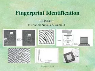
Peihao Huang, Chia-Yung Chang, Chaur-Chin Chen Department of Computer Science National Tsing Hua University Hsinchu, Taiwan 30013 E-mail: cchen@cs.nthu.edu.tw Implementation of An Automatic Fingerprint Identification System
Outline • A Flowchart of Fingerprint Identification ♪Type Classification ♪Minutia Points Detection ♪Minutiae Pattern Extraction ♪Pattern Matching ♦Rindex28, Lindex101 Databases ♦Experimental Results
Image Enhancement • The moisture and scars of a finger as well as the pressure due to a fingerprint sensing could distort the quality of the acquired fingerprint image. • We adopt an ad hoc strategy to enhance the quality of a fingerprint image. • Support that A (i, j) is image gray level at pixel (i, j), μ and s2 are the mean and variance of gray levels of input image, and α=150, γ=95, γ must satisfy γ>s. The enhanced image B( i , j ) is given as follows. • B( i , j ) α + γ * ([A ( i , j ) – μ]/s)
Orientation Computation(1) • First we apply a 5 by 5 median filtering on the image to avoid false gradient vectors generated by noise. • Then compute the gradient (Gx,Gy) at each pixel by a Sobel operator. mask Sobel Operation
Orientation Computation(2) The relationship between [Gx, Gy]T and [ρ,θ]T
Orientation Computation(3) • Because of opposite gradient vectors might offset each other, we double the angles of the gradient vectors before averaging each block, and let the length of the gradient vectors be squared. • Let be represented by • The average gradient in each block R (w×w)is
Orientation Computation(4) • The block gradient direction ψ is where is defined as:
Orientation Computation(5) Block orientation images
Region of Interest Detection(1) • To avoid obtaining false singular points or minutiae, we use mean and standard deviation in each block to determine if the block is “good” (not a marginal block) or not. where , and is the ratio of distance to the center of the fingerprint image. μ and σ are normalized to be in [0,1]. • If v > 0.8, the block is what we want.
Region of Interest Detection(2) Enhanced image Region of interest
Singular Point Detection(1) B3 B2 B1 1 1 1 1 2 1 B4 Bc B0 1 1 1 B5 B6 B7 • Because of noisy directions, we have to smooth the direction before computing the Poincaré index. • We regard the direction as a vector, double the angles and use a 3 by 3 averaging filter to smooth the direction. • The average direction of the block is
Singular Point Detection(2) P1 P8 P7 P2 P P6 P3 P4 P5 • We compute Poincaré index by summing up the difference in the direction surrounding the block P. For each block Pj, we compute the angle difference from 8 neighboring blocks along counter-clockwise direction. P1 → P2 → P3 → P4 → P5 → P6 → P7 → P8 → P1 Core if the sum of difference is 180° Delta if the sum of difference is -180°
Singular Point Detection(3) Singular points of Fingerprint Images
4+1 Fingerprint Type Classification Arch Left Loop Right Loop Whorl undecided
Implementation of classification • All Fingerprint Images are collected by a Veridicom FP110 reader with resolution 500 dpi • Experiment on Rindex28: 4x28 Right Index Fingerprint Images collected from 28 students • No classification error • Experiment on Lindex101 • 17 classification errors • Due to inappropriately pressing, too complex structure, or poor quality.
Inappropriately Pressing Whorl Left Loop
Inappropriately Pressing Right Loop Arch
Too Complex Structure • Left or Whorl Left or Arch
Image Binarization(1) • We have to distinguish valley and ridge of a fingerprint image before smoothing and thinning. So the gray value of pixels in the enhanced fingerprint image will be binarized to 0 or 255. • First we compute the gray value of P25 and P50 from the enhanced image, where Pk is the kth percentile of enhanced fingerprint image histogram. • Then we partition an enhanced fingerprint image into w by w blocks and compute the mean of each blocks. We define that Mj is the mean of the j-th block.
Image Binarization(2) • If the gray value of pixel Si is less than P25, we assign 0 to Si . If the gray value of pixel Si greater than P50, we assign 255 to Si . Otherwise, the pixel value is defined by the following rule:
Smoothing • After binarization, we find that there is still much noise on ridge region. In order to make the result of thinning better, we have to smooth the fingerprint image first. A smooth stage uses neighboring pixels to remove noise. • First a 5 by 5 filter is used. The pixel pi is assigned by: pi = { 255 if Σ5x5Nw≧18 0 if Σ5x5Nb≧18 pi otherwise • Then a 3 by 3 filter is further proceed by: pi = { 255 if Σ3x3Nw≧5 0 if Σ3x3Nb≧5 pi otherwise
(a) Original image (b) Enhanced image (c) Binarization image (d) Smoothed image
Thinning • The purpose of thinning stage is to gain the skeleton structure of fingerprint image. • It reduces a binary image consisting of ridges and valleys into a ridge map of unit width. (d) Smoothed image (e) Thinned image
Minutiae Detection • From a thinned image, we can classify each ridge pixel into the following categories according to its 8-connected neighbors. • A ridge pixel is called : • an isolated point if it does not have any 8-connected neighbor. • an ending if it has exactly one 8-connected neighbor. • an edgepoint if it has two 8-connected. • a bifurcation if it has three 8-connected. • a crossing if it has four 8-connected.
Minutiae Extraction Due to broken ridges, blur effects, and ridge endings near the margins of an image, we have to remove the spurious minutiae as described below. (1) Two endings are too close (within 8 pixels) (2) An ending and a bifurcation are too close (< 8 pixels) (3) Two bifurcations are too close (< 8 pixels) (4) Minutiae are near the margins (< 8 pixels)
Minutiae Extraction • Spurious minutia pixels include : (a) Ending that lie on the margins of the region of interest. (b) Two nearest endings with the same ridge orientation. (c) ending and bifurcation that are connected and close enough. (d) two bifurcations that are too close.
Minutiae Extraction (10) • Fingerprint Template Data The information format of fingerprint template data. The information format of singular points, core or delta. The information format of a minutia.
Fingerprint Matching Score The matching score of these two fingerprints is calculated by where M is the number of potential type-matching minutiae within a disk of a certain user-specified radius, R (about 8~16 pixels). r measures the distance between a pair of potentially matched minutiae points.
Fingerprint Matching (1) • Registration Point The registration point is regarded as the origin when processing minutiae matching. • Left Loop and Right Loop: its core is employed • Whorl: the coordinate of the upper-row core is utilized • Arch: we apply the mask shown as follows
Fingerprint Matching (2) • Minutiae Matching There are four steps involved in our matching process: (1) Check the type of fingerprint (2) Overlay by registration point (3) Rotate and relocate (4) Compute the matching score (5) Comparison (the larger match score, the better match)
Fingerprint Matching (3) The matching score of these two fingerprints is calculated by where M is the number of potential type-matching minutiae within a disk of a certain user-specified radius, R (about 8~16 pixels). r measures the distance between a pair of potentially matched minutia points.
Fingerprint Database (1) • Rindex28 Rindex28, is obtained from PRIP Lab at NTHU. It contains 112 images of size 300 by 300 contributed by 28 different individuals. Each contributed 4 times with the same right index finger scanned by a Veridicom FPS110 live scanner with 500 dpi
Fingerprint Database (2) • Lindex101 Lindex101, is obtained from PRIP Lab at NTHU. It contains 404 images of size 300 by 300 contributed by 101 different individuals. Each contributed 4 times with the same left index finger scanned by a Veridicom FPS110 live scanner with 500 dpi
Fingerprint Database (3) • FVC2000
Fingerprint Database (4) Examples of fingerprint images from each database of FVC2000
Experimental Results Rindex28 Lindex101 DB1 DB2 DB3 DB4 Recognition rate 99.11% 111/112 82.67% 334/404 92.50% 74/80 90.00% 72/80 87.50% 70/80 92.50% 74/80 Enrolling time for each fingerprint image 0.25 sec 0.25 sec 0.25 sec 0.25 sec 0.45 sec 0.17 sec Matching time 0.359 sec 3.14 sec 0.25 sec 0.218 sec 0.234 sec 0.156 sec The experimental results of 6 databases
Conclusion € We reveal three problems, which affect the result of an AFIS which merit further studies. (1) Noise produces the poor binarization results (2) Broken ridges result in the error orientation, which causes the misclassification of a fingerprint type (3) The shifted fingerprint image is difficult to match the minutiae pattern well, for example, the type misclassification due to the missing cores or deltas