xcvcxv
XC 64 Port Electronic Intelligent Patch Panel T1 to T1 Patch Panel. Product Presentation. xcvcxv. Orion Telecom Networks Inc. - 2010. Updated: Nov, 2010. Product Overview. Allows the user to cross-connect any T1 port to any T1 ports, electronically through

xcvcxv
E N D
Presentation Transcript
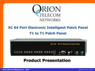
XC 64 Port Electronic Intelligent Patch Panel T1 to T1 Patch Panel Product Presentation xcvcxv Orion Telecom Networks Inc. - 2010 Updated: Nov, 2010
Product Overview • Allows the user to cross-connect any T1 port to any T1 ports, electronically through user executable software commands, without having to use any patch-cords or loosely hanging inter-connect cables. • Provides the user with the capability to uni-directionally broadcast T1 inputs to multiple T1 destinations • Also allows the user to re-route any T1 circuit to a secondary route (secondary T1 Port) in the event of the failure of the primary T1 route (primary T1 Port), without any human intervention and may be used as an "N"+1 protection switch • Accessed remotely over a TCP/IP link using Telnet. This allows the user to create / patch new circuits remotely and make new T1 cross-connections on the fly • SNMP V2 Traps are also generated over a UDP link, which allows the user to monitor the patch-panel and all T1 circuits remotely for any alarms
Where it should be used, who should use it and in which applications: • The XC 64 T1 electronic patch panel is designed to be used in Central Offices, Data Centers, Command and Control Centers, Remote Cell Sites, Utilities and Dealing Rooms seeking to eliminate the jungle of external patch-cords and loosely hanging wires which usually exists in locations where T1 patch-panels are installed. Why it should be used: • Easier Management - The XC 64 T1 electronic patch panel allows easier management of the T1 cross-connects since all cross-connects can be made and managed from a central location over TCP/IP or UDP Network using either CLI (text) commands, or a GUI or SNMP. • Efficient Management - The XC 64 T1 electronic patch panel allows a more efficient management since a log of all patches / cross-connects can be saved and archived as anMS (Microsoft) Access database files and retrieved and re-loaded whenever required. • Eliminates the need for labeling the patch-cords and inter-connected wires since all inter-connection records are automatically retained in the system's non-volatile memory. Additionally, the same can also be saved and archived as an MS (Microsoft) Access database file from the system's GUI.
XC 64 T1 Electronic Patch Panel – Back View: Option 1 with 3U high, rack-mountable RJ-45 (F) 19-inch shelf
XC 64 T1 Electronic Patch Panel – Back View: Option 2 with 2U high, rack-mountable DB-37 (F) 19-inch shelf
Highlights • 64 circuit, T1 to T1 electronic, remotely manageable patch panel • Allows the user to cross-connect between any T1 port to any T1 port, or any T1 port to multiple T1 Ports (in a broadcast mode only), electronically • Allows the user to re-route any T1 circuit to a secondary route (secondary T1 port) in theevent of the failure of the primary route (primary T1 port), without any human intervention • Hitless (automatic) switching between Primary T1 and Standby T1 links • Eliminates the use of the messy, loose, hanging inter-connect wires • Host of alarms for trouble shooting and maintenance • SNMP - V2 Traps / Alarms • Telnet and GUI based remote management features • Dual power inputs (1+1) to connect the equipment to two separate - 48V DC power sources for power source redundancy • Compact. Available in 19-inch, 2U shelf (DB37 connector) version, and a 19-inch, 3U shelf (RJ45 connector) version.
Status Monitoring • Status of alarms • Enabled / Disabled status of T1 ports • Monitoring of the XC 64 T1 Electronic Patch Panel status and configuration • SNMP - V2 Traps / Alarms. Programming Features • Enabling or disabling T1 channels (masking) of the T1 channels that are un-connected and not in use • Creating a cross connect between T1s using the Windows based, easy to use GUI • Telnet interface for remote programming by using text commands • SNMP - V2
Indications and Alarm Monitoring • Loss of incoming signal at any T1 Port • Configuration error alarm • 64 LED indicators to indicate the status of each T1 link • System's internal 3 Volts power supply present • External -48V DC input present • System Self Test Error.
System Management and Access • Windows XP and Windows 7 compatible Graphical User Interface (GUI) • Telnet - CLI (Command Line Interface) • SNMP V2 (MIB File provided with the equipment). Management and Control Port • Serial Management Port (RS232) - COM Port • USB Serial Port • 10/100BaseT for remote management over a LAN / TCP/IP network.
Thank you for your attention For more details visit us at our Website at http://www.oriontelecom.com Headquarters: Phoenix, Arizona Orion Telecom Networks Inc. 16810, Avenue of the Fountains, Suite # 108, Fountain Hills, AZ 85268 U.S.A. Phone: +1 480-816-8672, Fax: +1 480-816-0115 E-mail: sales@oriontelecom.com Website: http://www.oriontelecom.com Regional Office: Miami, Florida Orion Telecom Networks Inc. 4000 Ponce de Leon Blvd. Suite 470, Coral Gables, FL 33146 U.S.A. Phone: 1-305-777-0419, Fax: 1-305-777-0201 E-mail: sales@oriontelecom.com Website: http://www.oriontelecom.com