Chapter 7: Wireless LAN
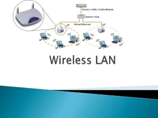
Chapter 7: Wireless LAN. What is Wireless LAN?. Wireless local area network (LAN) is a local area data network without wires. Wireless LAN is also known as WLAN in short.

Chapter 7: Wireless LAN
E N D
Presentation Transcript
What is Wireless LAN? Wireless local area network (LAN) is a local area data network without wires. Wireless LAN is also known as WLAN in short. WLAN is a high-speed data networking technology that is being widely deployed in residential network, enterprises, and public areas around the world. A WLAN creates extensions to cabling LAN and reduces the need for wireless connections. It transmits and receives data over electromagnetic waves using radio frequency (RF).
What is Wireless LAN? With it advantage and lack of wiring, mobile WLAN users can access real-time information and network resources easily. The WLAN ranges approximately 100 meters and is often used in building and on campuses. In short WLAN is a flexible data communication system providing wireless peer-to-peer and point-to-point connectivity within a building or campus. For that different types of technologies used for that which are show in the next slide figure.
Mobile Communication Technology according to IEEE (examples) WiFi 802.11a 802.11h 802.11i/e/…/n/…/z/aa Local wireless networks WLAN 802.11 802.11b 802.11g ZigBee 802.15.4 802.15.4a/b/c/d/e/f/g Personal wireless nw WPAN 802.15 802.15.5, .6 (WBAN) 802.15.3 802.15.3b/c 802.15.2 802.15.1 Bluetooth Wireless distribution networks WMAN 802.16 (Broadband Wireless Access) WiMAX + Mobility [802.20 (Mobile Broadband Wireless Access)] 802.16e (addition to .16 for mobile devices)
Advantages of WLAN • Flexibility: • Within radio coverage, node can communicate without further restriction. • Radio waves can penetrate walls, sender and receivers can be placed anywhere. • Sometimes wiring is difficult if firewalls separate building. • Penetration of a firewall is only permitted at certain points to prevent fire from spreading too fast.
Advantages of WLAN • Planning: • Only wireless ad-hoc networks allow for communication without previous planning any wired network needs wiring plans. • As long as devices follow the same standard they can communicate. • For wired network additional cabling with the right plugs and probably interworking unit have to be provided.
Advantages of WLAN • Design: • Wireless networks allow for the design of small, independent devices which can for example be put into a pocket. • Cables not only restrict users but also designers of small PDAs, notepads etc. • Wireless senders and receivers can be hidden in historic buildings i.e., current networking technology can be introduced without being visible.
Advantages of WLAN • Robustness: • Wireless network can survive disaster e.g., earthquakes or users pulling a plug. • If the wireless devices survive, people can still communicate. • Network requiring a wired infrastructure will usually break down completely.
Advantages of WLAN • Cost: • After providing wireless access to the infrastructure via an access point for the first user, adding additional users to a wireless network will not increase the cost. • This is, important for e.g. lecture halls, hotel lobbies or gate areas in airports where the numbers using the network may vary significantly. • Using fixed network, each seat in a lecture hall should have a plug for the network although many of them might not be used permanently. • Wireless connections do not wear out.
Disadvantages of WLAN • Quality of Service: • WLANs typically offer lower quality than their wired counterparts. • The main reasons for this are the lower bandwidth due to limitation in radio transmission, higher rates due to interference and higher delay/delay variation due to extensive error correction and detection mechanisms.
Disadvantages of WLAN • Proprietary solutions: • Due to slow standardization procedures many companies have come up with proprietary solution offering standardized functionality plus many enhanced features. • However, these additional features only work in a homogeneous environment i.e. when adapter from same vendors are used for all wireless nodes. • At least most components today here to the basic standard IEEE 802.11b or 8.2.11a.
Disadvantages of WLAN • Restrictions: • All wireless products have to comply with national regulations. • Several government and non-government institutions world wide regulate the operation and restrict frequencies to minimize interference. • WLAN are limited to low-power senders and certain license-free frequency bands, which are not the same worldwide.
Disadvantages of WLAN • Safety and Security: • Using radio waves for data transmission might interfere with other high-tech equipment in e.g. hospitals. • Senders and receivers are operated by laymen and radiation has to be low. • Special precautions have to be taken to prevent safety hazards. • The open radio interface makes eavesdropping much easier in WLANs than e.g. in the case of fiber optics.
Disadvantages of WLAN • Safety and Security: • All standard must offer encryption, privacy mechanisms , support for anonymity etc. • Otherwise more and more wireless networks will be hacked into as is the case already.
Design goals for wireless LANs • Global, Faultless operation • Low power for battery use • No special permissions or licenses needed to use the LAN • Robust transmission technology • Simplified spontaneous cooperation at meetings • Easy to use for everyone, simple management
Design goals for wireless LANs • Protection of investment in wired networks • Security (no one should be able to read my data), privacy (no one should be able to collect user profiles), safety (low radiation) • Transparency concerning applications and higher layer protocols, but also location awareness if necessary
Types of Transmission Technologies • Today two different basic transmission technologies can be sued to set up WLANs. • Infra red light: • This technology use diffuse light reflected at walls, furniture etc. or directed light if an line-of-sight (LOS) exists between sender and receiver. • Infrared system are simple in design, therefore it is inexpensive. • InfraLAN is an example of wireless LANs using infrared technology.
Types of Transmission Technologies Radio way: It is more popular and uses radio transmission in the GHz range. Almost all networks which are used any technology based on radio waves for data transmission. RF systems must used spread spectrum technology in the united states. This spread spectrum technology currently comes in two types : DSSS and FHSS. E.g. GSM at 900,1,800,1,900 MHz etc.
Comparison: infrared vs. radio transmission • Infrared Transmission • Advantages • simple, cheap, available in many mobile devices • no licenses needed • simple shielding possible • Radio Transmission • Advantages • experience from wireless WLAN and mobile phones can be used • coverage of larger areas possible (radio can penetrate walls, furniture etc.)
Comparison: infrared vs. radio transmission • Disadvantages • interference by sunlight, heat sources etc. • low bandwidth • Example • IrDA (Infrared Data Association) interface available everywhere • Disadvantages • very limited license free frequency bands • shielding more difficult, interference with other electrical devices • Example • Many different products
Modes of Wireless LAN Wireless works in two different modes: Infrastructure: Ad-hoc Network:
Infrastructure • The infrastructure mode includes one or several interconnected WLAN-cell, which are connected to a fixed net through an access point. • Wireless access points can be simply thought to function in a fashion analogous to Ethernet hub and switch are used to allow computers with wireless adapter to participate in a network. • All device to device wireless communication goes through the WAP. • This is referred to as infrastructure mode. • Next slide figure shows actual concept of WLAN modes.
Ad-hoc Networks The ad-hoc mode is WLAN-cell interacting without connection to wired networks, i.e. without connection to an access point. However the ad hoc networks work much like the Bluetooth. No access point is needed and the devices might connect to the internet through wired or other wireless techniques. Simple computing device to computing device wireless networking can be accomplished by installing a wireless network adapter (sometimes called wireless NICs) in each device. This is referred to as ad-hoc mode.
Comparison: infrastructure vs. ad-hoc networks infrastructure network AP: Access Point AP wired network AP AP ad-hoc network
802.11 - Architecture of an infrastructure network Portal Distribution System • Station (STA) • terminal with access mechanisms to the wireless medium and radio contact to the access point • Basic Service Set (BSS) • group of stations using the same radio frequency • Access Point • station integrated into the wireless LAN and the distribution system • Portal • bridge to other (wired) networks • Distribution System • interconnection network to form one logical network (EES: Extended Service Set) based on several BSS 802.11 LAN 802.x LAN STA1 BSS1 Access Point Access Point ESS BSS2 STA3 STA2 802.11 LAN
802.11 - Architecture of an ad-hoc network • Direct communication within a limited range • Station (STA):terminal with access mechanisms to the wireless medium • Independent Basic Service Set (IBSS):group of stations using the same radio frequency 802.11 LAN STA1 STA3 IBSS1 STA2 IBSS2 STA5 STA4 802.11 LAN
802.11 Protocol Architecture The 802.11 standards cover definitions for both MAC (medium access control) and Physical Layer. The standard currently defines a single MAC while interacts with three PHYs as follow: Frequency Hopping Spread Spectrum Direct Sequence Spread Spectrum Infrared. PHY layer one based on infrared and two layers based on radio transmission.
IEEE standard 802.11 fixed terminal mobile terminal infrastructure network access point application application TCP TCP IP IP LLC LLC LLC 802.11 MAC 802.11 MAC 802.3 MAC 802.3 MAC 802.11 PHY 802.11 PHY 802.3 PHY 802.3 PHY
IEEE 802.11 Sub layers Architecture and Management • Physical Layer Convergence Procedure (PLCP) • Physical Medium Dependent (PMD): Station Management LLC DLC MAC MAC Management PLCP PHY Management PHY PMD
802.11 Protocol Architecture:Physical Layer Architecture The architecture of the Physical layer comprises of the two sub layers for each station: Physical Layer Convergence Procedure (PLCP): PLCP sub layer is responsible for the Carrier Sense (CS) part of the Carrier Sense Multiple Access/Collision Avoidance (CSMA/CA) protocol. PLCP layer prepares the MAC Protocol Data Unit (MPDU) for transmission. The PLCP also delivers the incoming frames from the wireless medium to the MAC layer.
802.11 Protocol Architecture:Physical Layer Architecture PLCP appends fields to the MPDU that contains information needed by the physical layer transmitter and receiver. This frame is called PLCP Protocol Data Unit (PPDU). The structure of PLCP provides for asynchronous transfer of MPDU between stations. The PLCP header contains logical information that allows the receiving stations physical layer to synchronize with each individual incoming packet.
802.11 Protocol Architecture:Physical Layer Architecture Physical Medium Dependent (PMD): The PMD provides the actual transmission and reception of physical layer entities between stations through the wireless media. This sub layer provides the modulation/demodulation of the transmission.
802.11 Protocol Architecture:Physical Layer Architecture Frequency Hopping Spread Spectrum (FHSS): In FHSS mode this layer carries the clocking information to synchronize the receiver clock with the clock of the transmitted packet. Bellow figure depicts the FHSS PPDU packet. bits 80 16 12 4 16 variable synchronization SFD PLW PSF HEC payload PLCP preamble PLCP header
802.11 Protocol Architecture:Physical Layer Architecture the fields in the FHSS PLCP are as follows: SYNC: This field is made up of alternate zeroes and ones. This bit pattern is to synchronize the clock of the receiver. Start Frame Delimiter (SFD): This field indicates the beginning of the frame and the content of this field is fixed and always is 0000110010111101.
802.11 Protocol Architecture:Physical Layer Architecture PLCP Signaling (PSF): This field contains information about the data rate of the fields form whitened PSDU. The PLCP preamble is always transmitted at 1Mbps irrespective of the data rate of the wireless LAN. This field contains information about the speed of the link. For example 0000 means 1 Mbps and 0111 signifies 4.5 Mbps bandwidth.
802.11 Protocol Architecture:Physical Layer Architecture PSDU Length Word (PLW): This field specifies the length of the PSDU in octets. Header Error Check (HEC): This field contains the CRC (Cyclic Redundancy Check) according to CCITT CRC-16 algorithm.
802.11 Protocol Architecture:Physical Layer Architecture FHSS PMD is responsible for converting the binary bit sequence into analog signal and transmit the PPDU frame into the air. FHSS PDM does this using the frequency hopping technique. The 802.11 standard defines a set of channels within the ISM band for frequency hopping. Once the hopping sequence is set in the access point, stations automatically synchronize to the correct hopping sequence.
802.11 Protocol Architecture:Physical Layer Architecture Direct Sequence Spread Spectrum (DSSS): DSSS PLCP is responsible for synchronizing and receiving the data bits correctly. Bellow show a figure depicts the DSSS PPDU packet. bits 128 16 8 8 16 16 variable synchronization SFD signal service length HEC payload PLCP preamble PLCP header
802.11 Protocol Architecture:Physical Layer Architecture The fields in the DSSS PLCP are as following: SYNC: This field is made up of alternate zeroes and ones. This bit pattern is to synchronize the clock of the receiver with the received frame. Start Frame Delimiter (SFD): This field indicates the beginning of the frame and the content of this field is fixed and is always 1111001110100000.
802.11 Protocol Architecture:Physical Layer Architecture Signal: This field defines the type of modulation the receiver must use to demodulate the signal. When the value of this field is multiplied by 100 Kbps, we get the bandwidth of the transmission, The PLCP preamble and the header are always transmitted at 1 Mbps. The bandwidth defined by this field applies to MPDU field. Service: This field is not used and is usually 0.
802.11 Protocol Architecture:Physical Layer Architecture Length: This field contains an unsigned 16-bit integer indicating the length of the frame. However, unlike the FHSS this is not in octets. It is rather in microseconds. The receiver will use this to synchronize with the clock to determine the end of frame. Frame Check Sequence: This is a 16-bit checksum based on CCITT CRC-16 algorithm.
802.11 Protocol Architecture:Physical Layer Architecture DSSS PMD translates the binary digital sequence into analog radio signals and transmits the PPDU frame into the air. DSSS physical layer operates within the ISM band. If we take the 2.4 GHz band then it is between 2.4 GHz and 2.8435 GHz frequency band divided into multiple channels with 22 MHz width.
802.11 Protocol Architecture:Physical Layer Architecture Infrared: The PHY layer, which is based on infra red (IR) transmission, uses near visible light at 850-950 nm. The standard to require a line-of-sight between sender and receiver. This allows for point-to-multipoint communication. The maximum range is about 10 m if no sunlight or hear source interfere with the transmission, Typically, such a network will only work in buildings, e.g. classrooms, meeting room etc. Today no products are available that offer infra red communication based on 802.11.
802.11 Protocol Architecture:MAC Layer Architecture The MAC layer has to fulfill several tasks. First of all it has to control medium access, but it can also offer support for roaming, authentication and power conservation. Two basic services provided by the MAC layer: Asynchronous Data Service (mandatory) exchange of data packets based on “best-effort” support of broadcast and multicast Time-Bounded Service (optional) implemented using PCF (Point Coordination Function)
802.11 Protocol Architecture:MAC Layer Architecture The following three basic access mechanisms have been defined for IEEE 802.11: DFWMAC-DCF CSMA/CA (Distributed foundation wireless medium access control-Distributed coordination function)- (mandatory) collision avoidance via randomized „back-off“ mechanism minimum distance between consecutive packets ACK packet for acknowledgements (not for broadcasts)
802.11 Protocol Architecture:MAC Layer Architecture DFWMAC-DCF with RTS/CTS (optional) Distributed Foundation Wireless MAC avoids hidden terminal problem DFWMAC- PCF (Point coordination function) (optional) access point polls terminals according to a list
802.11 Protocol Architecture:MAC Layer Architecture Priorities: The standard defines 4 types of spacing intervals. These are called Inter Frame Spaces (IFS). Bellow show a figure Medium access and inter-frame spacing. DIFS DIFS PIFS SIFS medium busy contention next frame t direct access if medium is free DIFS
802.11 Protocol Architecture:MAC Layer Architecture IFSs are used to defer a station’s access to the medium and provide various levels of priorities: Short Inter Frame Space (SIFS): it is the shortest Inter Frame Space with the highest priority. RTS, CTS & Acknowledge use SIFS intervals. SIFS value is a fixed value per PHY and is calculated in such a way that the transmitting station will be able to switch back to receive mode and be capable of decoding the incoming packet.
802.11 Protocol Architecture:MAC Layer Architecture Point Coordination IFS (PIFS): It has medium priority to gain access to the medium. It is used for time-bounded service using PCF Distributed IFS (DIFS): It has lowest priority to gain access to the medium. It is used for asynchronous data service using PCF
802.11 Protocol Architecture:MAC Layer Architecture Basic DFWMAC-DCF (Distributed foundation wireless medium access control-Distributed coordination function) using CSMA/CA access method –I: station ready to send starts sensing the medium (Carrier Sense based on CCA, Clear Channel Assessment) if the medium is free for the duration of an Inter-Frame Space (IFS), the station can start sending (IFS depends on service type)