PHOS Alignment and Calibration Overview for ALICE Detector Modules
This document outlines the calibration and alignment requirements for the PHOS detector modules used in ALICE, particularly focusing on the geometry and spatial positioning of the modules. Each PHOS module consists of an Electromagnetic Calorimeter (EMC) and a Cherenkov Photon Veto (CPV). With a precision requirement of 1-2 mm, the document details the internal structure and fixed relative positions of components. The alignment data structure and modifications in geometry necessary for accurate tracking and particle identification are also discussed, highlighting the simplicity and efficiency of the alignment process.

PHOS Alignment and Calibration Overview for ALICE Detector Modules
E N D
Presentation Transcript
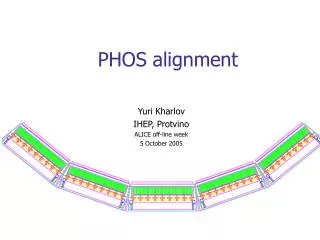
PHOS alignment Yuri Kharlov IHEP, Protvino ALICE off-line week 5 October 2005
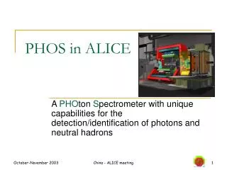
PHOS geometry PHOS has 5 modules Each module consists of EMC and CPV 1 EMC module contains 3584 crystals 1 CPV module contains 7168 pads PHOS calibration/alignment
Requirements for alignment • Coordinate resolution of PHOS is 1-2 mm • Internal structure of the modules is fixed and not a subject of survey nor alignment: • Crystals are assembled into modules in a hard structure with known position up to few tens of microns • Relative position of CPV and EMC is fixed • Modules are attached to a cradle and may need geometry parameters to store to CDB: • (x,y,z) of the module reference point (center?) in MARS • Rotation matrix of the modules in MARS • For particle identification the track extrapolation from TPC to PHOS is needed. Module position w.r.t. TPC is to be known to a precision not better than 1 mm. • Required precision can be provided by the optical survey which is valid until deinstallation of the detector. PHOS calibration/alignment
Alignment data structure class AliPHOSAlignData protected: Float_tfModuleCenterPosition[5][3]; // xyz position of a module centers in MARS Float_t fModuleAngles[5][3][2]; // Polar and azimuth angles for 3 axes of EMC // modules in MARS public: Float_t GetModuleCenterPosition(Int_t module, Int_t ixyz) Float_t GetModuleOrientation (Int_t module, Int_t ixyz, Int_t iangle) void SetModuleCenterPosition(Int_t module, Int_t ixyz, Float_t pos) void SetModuleAngle (Int_t module, Int_t ixyz, Int_t iangle, Float_t angle) Size of the object: 45 floats PHOS calibration/alignment
Existing geometry implementation in PHOS • Simulation geometry is still ideal and calculated from a minimum set of parameters • All PHOS modules are positioned in ALICE with 3 parameters: • Distance from IP to PHOS front cover (460 cm) • Angle between modules (20 degrees) • Number of modules (5) • Cells of the modules (5664) are produced by division of the modules into elements with fixed size (2.26 cm) • All other parameters are calculated from 3 basic ones: • Position azimuth angle of individual modules (-40, -20, 0, 20, 40) • (x,y,z) for individual module position in MARS • Rotation matrix (AliModule::AliMatrix()) of module orientation in MARS (1, 1, 2, 2, 3, 3) • Normal to the modules point strictly to IP, i.e. 1=0, 2=0, 2=0, 3,=90 • All transformations from global to local system and vice versa are reduced to rotation around z-axis PHOS calibration/alignment
Changes towards real geometry • AliPHOSGetter: to add AlignData() to retrieve AliPHOSAlignData from CDB • AliPHOSGeometry: to add a new data member AliPHOSAlignData *fAlignData • In AliPHOSGeometry::Init() modify to retrieve fAlignData from CDB via AliPHOSGetter::AlignData() • Calculate position coordinates (x,y,z) and orientation angles (1, 1, 2, 2, 3, 3) of individual modules • Modify AliPHOSGeometry::GetGlobal() to calculate rec.point position in MARS with real rotation matrices • Modify AliPHOSGeometry::Global2Local() to transform the point position in MARS into local system of module PHOS calibration/alignment
Conclusion • PHOS alignment is rather simple and reduced to 45 parameters. • Optical survey is enough to provide the necessary precision • Container class with alignment data is ready • Alignment data will be retrieved from CDB similar to calibration data (see Boris’ talk yesterday) • Changes in PHOS geometry are localized to about 5 functions and should be done ASAP PHOS calibration/alignment