Download
1 / 30
300 likes | 443 Vues
Lecture 18 VHDL Modeling of Sequential Machines. Prith Banerjee ECE C03 Advanced Digital Design Spring 1998. Outline. Describing Sequential Behavior in VHDL Latches Flip-Flops Finite State Machines Synthesis Using VHDL Using Packages in VHDL

E N D
Lecture 18 VHDL Modeling of Sequential Machines Prith Banerjee ECE C03 Advanced Digital Design Spring 1998 ECE C03 Lecture 18ECE C03 Lecture 6
Outline • Describing Sequential Behavior in VHDL • Latches • Flip-Flops • Finite State Machines • Synthesis Using VHDL • Using Packages in VHDL • READING: Dewey 17.1, 17.3, 17.4, 17.5, 17.6, 17.7, 17.8, 17.10, 18.1, 18.2 ECE C03 Lecture 18ECE C03 Lecture 6
Latches • Latches are easily described by using the concurrent signal assignment statement entity JK_LATCH is port ( J, K : in BIT; Q : inout BIT := ‘0’; Q_BAR : inout BIT := ‘1’;) end JK_LATCH; architecture TRUTH_TABLE of JK_LATCH is begin -- Map truth table into conditional concurrent statements Q <= Q when (J = ‘0’ and K = ‘0’) else ‘0’ when (J = ‘0’ and ‘K=‘1’) else ‘1’ when (J=‘1’ and K = ‘0’) else Q_BAR; Q_BAR <= not Q; end TRUTH_TABLE; J K Q+ 0 0 Q 0 1 0 1 0 1 1 1 Q/ ECE C03 Lecture 18ECE C03 Lecture 6
Level-sensitive Synchronous Behavior • When a control signal like a clock controls whether the gated latch responds to inputs entity JK_GATED_LATCH is port ( J, K, CLK : in BIT; Q : inout BIT := ‘0’; Q_BAR : inout BIT := ‘1’;) end JK_LATCH; architecture TRUTH_TABLE of JK_GATED_LATCH is begin CLKED : block (CLK = ‘) -- guard expression begin Q <= guarded Q when (J = ‘0’ and K = ‘0’) else ‘0’ when (J = ‘0’ and ‘K=‘1’) else ‘1’ when (J=‘1’ and K = ‘0’) else Q_BAR; Q_BAR <= not Q; end block CLKED; end TRUTH_TABLE; ECE C03 Lecture 18ECE C03 Lecture 6
Block Statements • A block statement provides a way to combine a group of concurrent statements together • A group of statements can be placed under a guard • FORMAT label: block (guard expression) -- declarative part begin -- statement part end block label • A guard is a boolean expression that evaluates to true or false. • Concurrent statements in block execute if guard is true ECE C03 Lecture 18ECE C03 Lecture 6
Guarded Statement • A guarded assignment statement executes if either • (1) the guard expression changes from FALSE to TRUE • (2) The guard expression is TRUE and one of the signals appearing on the right hand side of the signal assignment changes value • Example: B1 : block (CONTROL_SIGNAL = ‘1’) begin X <= guarded A or B after 5 min; Y <= A or B after 5 min; end blcok B1 ECE C03 Lecture 18ECE C03 Lecture 6 5 10 15 20 25 30 35
Flip-flops • Edge-triggered flip-flops are controlled by signal transitions, latches are controlled by levels. entity JK_FF is port ( J, K, CLK : in BIT; Q : inout BIT := ‘0’; Q_BAR : inout BIT := ‘1’;) end JK_LATCH; architecture DATA_FLOW of JK_FF is begin CLKED : block (CLK = ‘1’ and not CLK’STABLE) -- guard expression begin Q <= guarded Q when (J = ‘0’ and K = ‘0’) else ‘0’ when (J = ‘0’ and ‘K=‘1’) else ‘1’ when (J=‘1’ and K = ‘0’) else Q_BAR; Q_BAR <= not Q; end block CLKED; end DATA_FLOW; ECE C03 Lecture 18ECE C03 Lecture 6
Predefined Signal Attributes • VHDL provides several predefined attributes which provide information about the signals signal_name’ACTIVE: indicates if a transaction has occurred signal_name’QUITE: indicates that transaction has not occurred signal_name’EVENT : If an event has occurred on signal_name signal_name’STABLE: If an event has not occurred signal_name’LAST_EVENT: Time elapsed since last event has occurred signal_name’DELAYED(T): A signal identical to signal_name but delayed by T units of type TIME; ECE C03 Lecture 18ECE C03 Lecture 6
Setup and Hold Times • Setup and hold times are timing restrictions placed on synchronous sequential systems • Use assertions in VHDL to describe requirements architecture DATA_FLOW of D_FF is begin assert not (CLK’DELAYED(HOLD) = ‘1’ and not CLK’DELAYED(HOLD)’STABLE and not D’STABLE(SETUP+HOLD) report “Setup/Hold Timing Violation”; CLKED: block (CLK = ‘1’ and not CLK’STABLE) Q <= guarded D; Q_BAR <= not Q; Q_BAR <= not Q; end DATA_FLOW; CLK CLK’DELAYED(HOLD) D Setup Hold ECE C03 Lecture 18ECE C03 Lecture 6
Synchronous Finite State Machines • Consider example of binary counter Z0 A Z1 B Z2 C ECE C03 Lecture 18ECE C03 Lecture 6
Data flow VHDL Modeling of Counter entity BIN_COUNTER is port (CLK : in BIT; Z : out BIT_VECTOR(2 downto 0)); end BIN_COUNTER; architecture DATA_FLOW of BIN_COUNTER is type FF_INDEX is (A, B, C); type FF_TYPE is array (FF_INDEX) of BIT; signal Q : FF_TYPE; begin DFF: block (CLK = ‘1’ and not CLK’STABLE) -- rising edge begin -- State D flip flops Q(A) <= guarded (Q(A) and not Q(B) ) or (Q(A) and not Q(C)) or (not Q(A) and Q(B) and Q(C); Q(B) <= guarded Q(B) xor Q(C); Q(C) <= guarded not Q(C); end block DFF; -- output function Z <= Q(A) & Q(B) & Q(C); end DATA_FLOW; ECE C03 Lecture 18ECE C03 Lecture 6
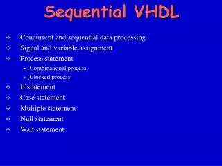
Algorithmic Modeling of State Machines • Until now, we showed state machines being modeled by data flow (using concurrent statements) • We will describe using algorithmic or procedural form using conventional programming language semantics • process statements • wait statements • variable and signal assignments • if and case statements • loop statements ECE C03 Lecture 18ECE C03 Lecture 6
Binary Counter State Diagram S0 000 S1 001 S7 111 S6 110 S2 010 S5 101 S3 011 S4 100 ECE C03 Lecture 18ECE C03 Lecture 6
VHDL Model of Counter architecture ALGORITHM of BIN_COUNTER is begin process variable PRESENT_STATE: BIT_VECTOR(2 downto 0) := B”111”; begin case PRESENT_STATE is when B”000” => PRESENT_STATE := B”001”; when B”001” => PRESENT_STATE := B”010”; when B”010” => PRESENT_STATE := B”011”; when B”011” => PRESENT_STATE := B”100”; when B”100” => PRESENT_STATE := B”101”; when B”101” => PRESENT_STATE := B”110”; when B”110” => PRESENT_STATE := B”111”; when B”111” => PRESENT_STATE := B”000”; end case; Z <= PRESENT_STATE after 10 nsec; wait until (CLK = ‘1’; end process; end ALGORITHM; ECE C03 Lecture 18ECE C03 Lecture 6
VHDL Model of FSMs for Synthesis • One can define a VHDL model of a FSM (Mealy Machine) using two processes • One for the combinational logic for the next state and output functions • One for the sequential elements Output logic function Primary inputs Next state Logic function Presnt state Memory elements, FFs ECE C03 Lecture 18ECE C03 Lecture 6
Architecture Body of FSM architecture rtl of entname is subtype state_type is std_ulogic_vector(3 downto 0); constant s0 : state_type := "0001"; constant s1 : state_type := "0010"; constant s2 : state_type := "0100"; constant s3 : state_type := "1000"; signal state, next_state : state_type; signal con1, con2, con3 : std_ulogic; signal out1, out2 : std_ulogic; signal clk, reset : std_ulogic; -- process comb logic -- process state registers end architecture rtl; s0 s1 s2 s3 ECE C03 Lecture 18ECE C03 Lecture 6
Process Statements for Comb/State Reg Logic when s3 => if con2 = '0' then next_state <= s3; elsif con3 = '0' then out1 <= '0'; next_state <= s2; else next_state <= s1; end if; when others => null; end case; end process state_logic; state_register : process (clk, reset) is begin if reset = '0' then state <= s0; elsif rising_edge(clk) then state <= next_state; end if; end process state_register; begin state_logic : process (state, con1, con2, con3) is begin case state is when s0 => out1 <= '0'; out2 <= '0'; next_state <= s1; when s1 => out1 <= '1'; if con1 = '1' then next_state <= s2; else next_state <= s1; end if; when s2 => out2 <= '1'; next_state <= s3; ECE C03 Lecture 18ECE C03 Lecture 6
Use of VHDL in Synthesis • VHDL was initially developed as a language for specification and simulation and modeling • Recently being used as a language for hardware synthesis from logic synthesis companies • Synopsys Design Compiler, Ambit BuildGates, Mentor Graphics Autologic, .. • Synthesis tools take a VHDL design at behavioral or structural level and generate a logic netlist • Minimize number of gates, delay, power, etc. Area delay ECE C03 Lecture 18ECE C03 Lecture 6
Synthesizable Subset of VHDL • There are a number of constructs that cannot be synthesized into hardware • File operations including textio • Assertion statements • There are some generally accepted ways of entering VHDL descriptions such that it correctly synthesizes the logic ECE C03 Lecture 18ECE C03 Lecture 6
Synthesizable VHDL • Most synthesis tools can take in a structural VHDL specifying flip-flops and gates explictly and then minimize the design • When one tries to do true synthesis, i.e. specify a design in behavioral form, then not all tools can recognize and synthesize correct logic • Example: all synthesis tools recognize the rising edge of a clock signal if specified as: • rising_edge(clk) <=> clk’event and clk = ‘1’ • If specified otherwise, tools do not recognize clock edge ECE C03 Lecture 18ECE C03 Lecture 6
DFF1: process (clk) is begin if rising_edge(clk) then q <= d; end if; end process; THIS IS RECOGNIZED AS A FF BY MOST TOOLS DFF2: process is begin wait until rising_edge(clk)l q <= d; end process; DFF3: q <= d when rising_edge(clk) else q; DFF4: block (rising_edge(clk) and not clk’stable) is begin q <= guarded d; end block; Four ways of specifying DFF ECE C03 Lecture 18ECE C03 Lecture 6
Registered Comparator • The devices stores result of comparison of two inputs a and b on rising clock edge Process (clk) is begin if (a=b) then d := ‘1; else d := ‘0’; end if; if rising_edge(clk) then q <= d; end if; end process; THIS WILL NOT SYNTHESIZE SINCE PROCESS EXECUTES FOR BOTH EDGES OF CLOCK Process(clk) is begin if rising_edge(clk) then if (a=b) then q <= ‘1’; else q <= ‘0’; end if; end process; THIS WILL CORRECTLY SYNTHESIZE SINCE ASSIGNMENT HAPPENS ON RISING EDGE OF CLOCK ECE C03 Lecture 18ECE C03 Lecture 6
Examples of Correct Synthesis • To synthesize a simple logic gate: y <= a or b; • To implement a multiplexer: y <= a when x = ‘1’ else b; ANOTHER WAY: case x is when x = ‘1’ => y <= a; when x = ‘0’ => y <= b; end case; • To implement a DFF process (reset, clk) is begin if reset = ‘1’ then q <= 0; elseif rising_edge(clk) then q <= d; end if; end process; ECE C03 Lecture 18ECE C03 Lecture 6
Implied Latches in VHDL Descriptions • EXAMPLE of a Multiplexer where all cases specified, I.e. y gets a new value in all cases, hence is a combinational logic: case x is when x = ‘1’ => y <= a; when x = ‘0’ => y <= b; end case; • EXAMPLE of a D latch where for one case, output not specified, implied that previous value retained case x is when x = ‘1’ => y <= a; end case; a b y x a d q y clk x ECE C03 Lecture 18ECE C03 Lecture 6
Examples of Wrong VHDL Synthesis • Given a statement y <= a + b + c + d; • Synthesis tool will create a tree of adders by adding a + b, then adding to c, and then to c; • Instead if specified as y <= (a +b) + (c +d); • the synthesis tool will be forced to synthesize a tree of depth 2 by adding (a+b), and (c+d) in parallel, then adding results together. • Another mistake y <= a or b or c and d; • Instead write as y <= (a or b) or (c and d); ECE C03 Lecture 18ECE C03 Lecture 6
Use of Packages in VHDL • A VHDL package is simply a way of grouping a collection of related declarations that serve a common purpose • Can be reused by other designs package identifier is {package declaration} end package identifier; ECE C03 Lecture 18ECE C03 Lecture 6
Predefined Packages • The predefined types in VHDL are stored in a library “std’ • Each design unit is automatically preceded by the following context clause library std, work; use std.standard.all; package standard is type boolean is (false, true); -- defined for operators =, <=, >=, .. type bit is (‘0’, ‘1’); -- defined for logic operations and, or, not… type character is (..); type integer is range IMPLEMENTATION_DEFINED; subtype natural is integer range 0 to integer’high; type bit_vector is array(natural range <>) of bit; … end package standard; ECE C03 Lecture 18ECE C03 Lecture 6
Package IEEE Standard 1164 • IEEE standard is based on multi-valued logic type and standard logic gates type std_ulogic is (‘U’ -- uninitialized ‘X’ -- forcing unknown ‘0’ -- forcing zero ‘1’ -- forcing one ‘Z’ -- high impedance ‘W’ -- weak impedance ‘L’ -- weak zero ‘H’ -- weak one ‘-’ -- don’t care); Include a line before each entity or architecture body library ieee; use ieee.std_logic1164.all; ECE C03 Lecture 18ECE C03 Lecture 6
Package IEEE Standard 1164 type std_ulogic_vector is array (natural range <>) of std_ulogic; function resolved (s: std_ulogic_vector) return std_ulogic; subtype UX01 is resolved std_ulogic range ‘U’ to ‘1’; -- U, X, 0, 1 function “and” (l : std_ulogic; r : std_ulogic) return UX01; function “and” (l : std_ulogic_vector; r : std_ulogic_vector) return std_ulogic_vector; function To_bit (s : std_ulogic; xmap : bit := ‘0’) return bit; function rising_edge(signal s: std_logic) return boolean; ECE C03 Lecture 18ECE C03 Lecture 6
Summary • Describing Sequential Behavior in VHDL • Latches • Flip-Flops • Finite State Machines • Synthesis Using VHDL • Using Packages in VHDL • NEXT LECTURE: Case Study: Pipelined Multiplier Accumulator • READING: P. Ashenden, “The Designer’s Guide to VHDL”, Morgan Kaufmann, Chapter 6 ECE C03 Lecture 18ECE C03 Lecture 6