Download
1 / 15
150 likes | 188 Vues
Understand the process of rectification in converting AC to DC, with comprehensive analysis of full wave rectifiers using diodes and transformers. Learn about rectifier circuits, working principles, advantages, disadvantages, and filter types.

E N D
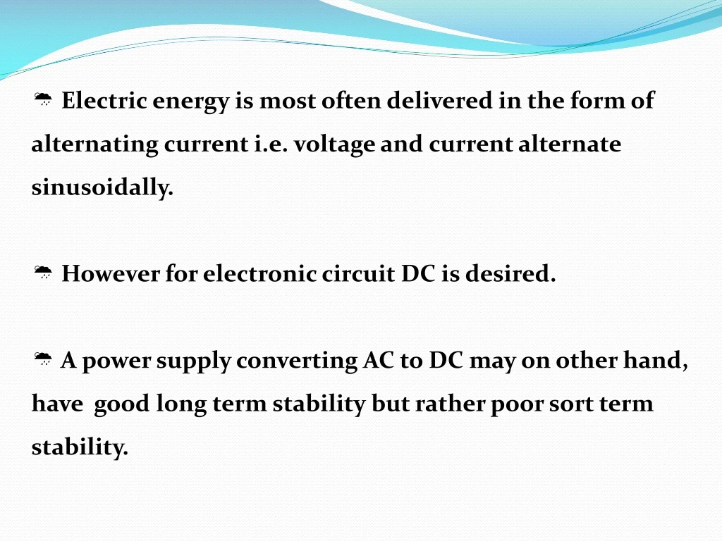
Electric energy is most often delivered in the form of alternating current i.e. voltage and current alternate sinusoidally. • However for electronic circuit DC is desired. • A power supply converting AC to DC may on other hand, have good long term stability but rather poor sort term stability.
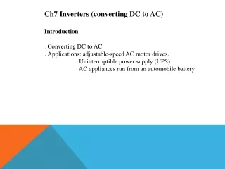
Rectification :- The process of converting AC voltage into DC voltage is called rectification. The circuit use for this conversion is called rectifier.
The transformer delivers an alternating voltage. • In order to get DC , we must get rid of one • half of the voltage. This can be done by • using a diode. Half Wave rectifier Full wave rectifier
Full Wave Rectifier Full Wave Rectifier Using Two Diode:- A full wave rectifier is a combination of two half wave rectifier circuit. Such circuit requires a step dawn transformer with centre tapped. Two diode connected to the two terminals of secondary of a transformer. The load RL is connected between centre tapped terminal and diodes as shown in fig.
Working Of Full Wave Rectifier Using Two Diodes • During positive half cycle of AC input say s1is positive with respect to s2 the diode D1 become forward biasedand it conduct. Thus, the current flow along the path S1D1ABOS1. Fig. Circuit diagram
During negative half cycle of the AC input , now polarities will be reversed. The terminal S1 become negative and S2 positive which enable the diode D2 to conduct as it becomes forward biased and D1 do not conduct. Thus the current flow along the path S2D2ABOS2 . Fig. Wave form of input and output
Analysis Of Full Wave Rectifier • Due to centre tapped transformer the secondary voltage split up into two part : • V1 = Vm Sin wt • v2= Vm Sin(wt-π) • Im =vm/(RL + RF)
1. Average DC (Idc ): Idc = 2Im / π R.M.S. Value of current (Irms ) : Irms =Im/ √2 3. AC input power (Pi ): Pi=I2m (RL +Rf)/2 4. DC output power(Pdc): Pdc= 4I2mRL/π2 5. Rectification efficiency(ŋ): ŋ=81.2%
Rippal factor (γ): • γ= 0.482 Peak inverse voltage (PIV) :- PIV =2Vm
Full wave Rectifier using four diode:- S1 S1 S2 S2
Working :- • Suppose during positive half cycle of AC input S1 terminal of secondary is positive with respect to S2, hence diodes D1 and D3 will be forward biased. • During negative half cycle of AC input S2 terminal of secondary is positive with respect to S1 and diodes D2 and D4 will be forward biased. Vi Vo Fig. Wave forms of input and output
Advantages:- The full wave bridge rectifier needs smaller transformer as compared with that of needed for full wave rectifier using two diodes. The rectifier do not require centre tapped transformer. For same DC output, diodes with smaller PIV rating can be used because the peak inverse voltage is one half that of the center tapped circuit using two diodes. Disadvantages:- Two extra diode are required. Voltage regulation is poor.
Filters :- The electrical components used to minimize ripple in the rectifier output are called filter. The common types of filters are as follows : 1. Capacitor filter 2. Inductor (Choke) filter 3. L-section filter 4. π-Section filter
For examples:- Inductor filter (Choke as a filter):-