Download
1 / 22
220 likes | 583 Vues
Optimal design and operation of a Draft Tube Spouted Bed Reactor for a photocatalytic process David Follansbee , John Paccione, Lealon Martin. Environmental Division Fundamentals of Environmental Systems Engineering . Tuesday, November 6, 2007. Outline . Motivation for process

E N D
Optimal design and operation of a Draft Tube Spouted Bed Reactor for a photocatalytic process David Follansbee, John Paccione, Lealon Martin Environmental Division Fundamentals of Environmental Systems Engineering Tuesday, November 6, 2007
Outline Motivation for process Process Model Parameters and Problem statement Results Conclusion and Future Work
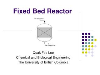
Traditional photocatalytic Reactors Photocatalytic slurry reactors Batch configuration Photocatalyst particle separation Photocatalyst loading limitations Photocatalytic fixed bed reactors Cross sectional area limitations Longer reactor length for increase throughput High pressure drops Mass transfer and kinetics are coupled Photocatalyst coating of reactor walls Cross sectional and mass transfer limitations
Motivation for DTSMB Decoupling of mass transfer from kinetics Continual degradation of contaminant and regeneration of photocatalyst Counter-current design Photocatalyst immobilized on large, dense particles UV Jet flow Draft tube Clean water outlet Dirty Water inlets
Process block diagram Design Parameters Gp . xo WUV Gfd Target Parameters Gfa yo Performance variables Gp xi εD Key design variables DA Dt M HA εA Gfd Gp . xo Gfa yi WPump Photo Reactor Draft tube Packed bed reactor
Annular bed Model Assumptions: Counter current contact Constant fluid properties Costant particle size and density Langmuir adsorption: Mass load : Gp Gp Mass balance: xi xo DA GA M HA yo Log mean concentration difference: H HA GA Height: yi GA yi Gp xi GA yo Gp xo GA yi A.Y. Khan. Titanium dioxide coated activated carbon: Masters thesis, University of Florida, 2003. V. Manousiouthakis and L. L. Martin. Computers & Chemical Engineering, 28(8):1237–1247, July 2004.
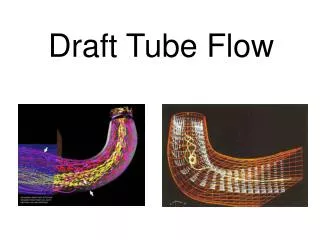
Draft tube model • Assumptions • Only non-accelerating portion of bed Mass flowrate of fluid: Mass flow rate of particles: Fluid-particle interphase drag coefficient: Slip velocity: Pressure Drop Gp GfD Dt Ht εD Gp GfD Z.B. Grbavcic, R.V. Garic, D.V. Vukovic, D.E. Hadzismajlovic, H.Littman, M.H. Morgan, and S.D. Jovanovic. Powder Technology, 72(2):183–191, Oct. 1992.
UV model (Intensity, Power, and Kinetics) Modeled as a PFR Pseudo first order reaction No mass transfer limitations . WUV Mass flow rate: Rate equation: I Intensity (Lambert-Beer Law): Adsorption coefficient: Power required: Gp xo DUV HUV Io Gp xi
Operation limitations and specifications • Mass flowrate can not exceed an upper limit where particles will not settle in annular bed • Gp<(1-mf)Aapva(max) • Voidage in the draft tube has to be above a critical collapsing voidage and below 1 • vc< D<1 • The fluid velocity has to be great enough to ensure transport of particles • u1.5vt
Test System Reactive Red degradation 2 mm catalyst particles TiO2/AC photocatalyst composites SiO2 substrate
Model Constants Z.B. Grbavcic, R.V. Garic, D.V. Vukovic, D.E. Hadzismajlovic, H.Littman, M.H. Morgan, and S.D. Jovanovic. Hydrodynamic modeling of vertical liquid solids flow. Powder Technology, 72(2):183–191, Oct. 1992.
Problem Statement Given: Adsorptive mass transfer rates Contaminant degradation rates The annular flowrate and inlet concentration Target concentration Minimize
Schematic of Algorithm Physical Properties Design Parameters Operation specs Interval analysis Math Model Optimal design and operating conditions Sensitivity Analysis Sensitivity Analysis Minimizing objective function
Conclusion Height of annular bed is insensitive to change in mass flowrate. Operating at a low mass flowrate (<0.1 kg/s) allows for the most robust performance. For the test system of TiO2/AC UV cost is high Motivates for optimization of catalyst properties i.e. density, UV adsorption, and kinetics Model must be experimentally validated Specifically the kinetics and mass transfer models
Acknowledgements Dr. Howard Littman Dr. Joel Plawsky Dr. David Dziewulski (DOH and SUNY school of Public health) Martin Research Group RPI funding Department of Defense