Download
1 / 16
650 likes | 2.35k Vues
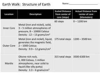
MEASUREMENT OF EARTH RESISTANCE. Design of Earthing System …. Purpose of earthing…… Safety of the living beings around the vicinty of the substation Proper functioning of the protection system under fault condition To limit the touch and step potential within tolerable limits. 0.116. √t.

E N D
Design of Earthing System… • Purpose of earthing…… • Safety of the living beings around the vicinty of the substation • Proper functioning of the protection system under fault condition • To limit the touch and step potential within tolerable limits
0.116 √t Human Safety Current RangeEffects on Humans • 1 mA Threshold of perception • 1-6 mA Let go currents • 9-25 mA Pain full, hard to let go • 25-60 mA Muscular contractions • 60-100 mA Ventricular fibrillation Maximum Body Current: Ik = for t = .03s to 3s
Soil Resistivity Measurement Wenner Four-Pin Method: Four probes are driven into the earth along a straight line, at equal distances ‘a’ apart , driven to a depth ‘b’. The voltage between the two inner (potential, V) electrodes is then measured and divided by the current between the two outer (current, I) electrodes to give a value of resistance R.
Soil Resistivity Measurement Then, 4aR a = ______ 1+ 2a - a_ (a2+4b2) (a2+b2) where, a is the apparent resistivity of the soil in -m R is the measured resistance in a is the distance between adjacent electrodes in metres b is the depth of the electrodes in m
Conductor Size Calculation… The area of the conductor of earthing mat is given by: If . (tc.r.r.104/Tcap) Ac2 = ln {1+ (Tm-Ta)/(K0+Ta)} where, If is the symmetrical fault current in KA (rms), the maximum current that would flow in any section of the earthing system tc is the duration of fault current in sec.
Conductor Size Calculation… ris the co-efficient of linear expansion of the earthinging conductor r is the resistivity of the earthing conductor in - cm at reference temperature, Tr Tcap is the thermal capacity factor of the earthing conductor in Joules/ cm2/ 0C Tr is the reference temperature=200C K0 = [(1/r) - Tr] Ta is the ambient temperature Tm is the maximum allowable temperature for joints
Calculation of resistance of the earthing grid 1 1 1 RG=. + 1 + LM (20xAe) 1+h(20/Ae) Where, Ae is the area of the ground mat. h is the depth of burried conductor LM is the length of the total buried conductor
Calculation of tolerable touch potential… Etouch = (1000+1.5xCsxs ).(0.116/ts) Estep = (1000+6.0xCsxs ).(0.116/ts) Where, ts is the duration of shock current & Cs is the surface layer derating factor and is given by: 0.09 (1- /s) Cs = 1 – 2hs+0.09 is the soil resistivity of the substation s is the surface layer (gravel) resistivity
Calculation of attainable touch potential… The attainable touch (mesh) potential is calculated by the following expression; . Km. Ki. IG Em = LM Where, Km is the spacing factor for mesh voltage Ki is the correction factor for grid geometry LM is the effective length of the burried earthing conductor IG is the maximum grid current
Calculation of attainable step potential… The attainable step potential is calculated by the following . Ks. Ki. IG Es = LS Where, Ks is the spacing factor for step voltage Ki is the correction factor for grid geometry and LS is the effective length of LC+LR for step voltage in metres IG is the maximum grid current
For Safe design…. Em<Etouch & Es<Estep Etransfered(=IG.RG) should be within limit