Crystal Structure
Crystal Structure. Crystal Properties of Semiconductors. d. f. i. c. a. t. i. o. n. o. f. a. p. o. l. y. c. r. y. s. t. a. l. l. i. n. e. s. o. l. i. d. f. r. o. m. t. h. e. m. e. l. t. . (. a. ). N. u. c. l. e. a. t. i. o. n. . (. b. ).

Crystal Structure
E N D
Presentation Transcript
d f i c a t i o n o f a p o l y c r y s t a l l i n e s o l i d f r o m t h e m e l t . ( a ) N u c l e a t i o n . ( b ) r o w h . ( c ) T h e s o l i d i f i e d p o l y c r y s t a l l i n e s o l i d . F o r S c s i m p l i i t y , c u b e s r e p r e s e n t a t o m s .
Crystal Properties of Solid r e a d d t o t h e r e s i s t i v i t y b y M a t t h i e s s e n ' s r u l e . F o r a v e r y g r a i n y s o l i d , t h e e l e c t r o n i s s c a t t e r e d f r o m g r a i n b o u n d a r y t o g r a i n b o u n d a r y a n d t h e m e a n f r e e p a t h i s a p p r o x i m a t e l y e q u a l t o t h e m e a n g r a i n d • Polycrystalline G r a i n 1 G r a i n 2 G r a i n B o u n d a r y (a) ( b ) G r a i n b o u n d a r i e s c a u s e s c a t t e r i n g o f t h e e l e c t r o n a n d t h e r e f o i a m e t e r .
Crystal Properties of Solid S t r a i n e d • Polycrystalline F o r e i g n i m p u r i t y S e l f - i n t e r s t i t i a l t y p e a t o m V o i d , v a c a n c y b o n d G r a i n b o u n d a r y B r o k e n b o n d ( d a n g l i n g b o n d ) T h e g r a i n b o u n d a r i e s h a v e b r o k e n b o n d s , v o i d s , v a c a n c i e s , s t r a i n e d b o n d s a n d " i n t e r s t i t i a l " t y p e a t o m s . T h e s t r u c t u r e o f t h e g r a i n b o u n d a r y i s d i s o r d e r e d a n d t h e a t o m s i n t h e g r a i n b o u n d a r i e s h a v e h i g h e r e n e r g i e s t h a n t h o s e w i t h i n t h e g r a i n s .
Examples of Crystals Snow Quartz Copper oxide Salt (NaCl) crystal Gold (Au) crystals at 1000 C
Examples of Crystals Salt (NaCl) crystal
Examples of Crystals Carbon Nanotube Carbon Nanofiber Fullerene TEM image of Carbon Nanotube
Examples of Crystals Single crystal Diamonds. Single crystal Silicon.
Atomic Resolution Images of Solid Surfaces • STM (Scanning Tunneling Microscope) images of solid surface Silicon (Si) surface Iron silicide surface
Atomic Resolution Images of Solid Surfaces • 3D-STM (Scanning Tunneling Microscope) images of solid surface Silicon (Si) surface Hydrogen bonds on a Silicon surface.
Atomic Resolution Images of Solid Surfaces • TEM (Tunneling Electron Microscope) images of solid surface High resolution image of a quasiperiodical grain boundary in gold.
Crystal Structures and Definitions • Lattice : The periodic arrangement of the atoms. • Unit Cell: Representative of the entire lattice and is regularly repeated throughout the crystal. • Primitive Cell: Smallest unit cell which can be repeated to form the lattices. a a/2 Primitive Cell Unit Cell Each crystal built up of a repetitive stacking of unit cells each identical in size, shape, and orientation with every other one.
Crystal Structures and Definitions • Coordinates of position in the unit cell • x, y, z expressed in terms of the unit cell edges. • Example • reached by moving along the axis a distance of • 3x the length of the vector , the parallel to , a distance 2 , • and finally parallel to , a distance equal to the length of .
Crystal Lattice Group z U n i t C e l l G e o m e t r y c a c b b O y g a a b x • Bravais lattices Length and Angle Triclinic abc 90 K2CrO7 Monoclinic abc ==90-S, CaSO42H2O Orthorhombic abc ===90-S, Ga, Fe3C Tetragonal a=bc ===90-Sn, TiO2 Cubic a=b=c ===90 Cu, Ag, Zn, NaCl Hexagonal a1=a2=a3c ==90, =120 Zn, Cd Rhombohedral a=b=c ==90 As, Sb, Bi
Crystal (Bravais) Lattice Group (I) Triclinic a≠b≠c, ≠≠≠90°
T h e s e v e n c r y s t a l s y s t e m s ( u n i t c e l l g e o m e t r i e s ) a n d f o u r t e e n B r a v a i s l a t t i c e s . n y m e t a l s , A l , C u , F e , P b . M a n y c e r a m i c s a n d s e m i c o n d u c t o r s , N a C l , C s C l , L i F , S i , G a A s S i m p l e c u b i c B o d y c e n t e r e d F a c e c e n t e r e d c u b i c c u b i c T E T R A G O N A L S Y S T E M a b g a b c = = = = 9 0 ° B o d y c e n t e r e d S i m p l e t e t r a g o n a l t e t r a g o n a l I n , S n , B a r i u m T i t a n a t e , T i O 2 O R T H O R H O M B I C S Y S T E M a b g a b c = = = 9 0 ° S , U , P l , G a ( < 3 0 ° C ) , I o d i n e , C e m e n t i t e ( F e C ) , S o d i u m S u l f a t e 3 S i m p l e B o d y c e n t e r e d F a c e c e n t e r e d B a s e c e n t e r e d o r t h o r h o m b i c o r t h o r h o m b i c o r t h o r h o m b i c o r t h o r h o m b i c R H O M B O H E D R A L S Y S T E M H E X A G O N A L S Y S T E M a b g a b c a b g = = = = 9 0 ° a b c = = = 9 0 ° ; = 1 2 0 ° A r s e n i c , B o r o n , B i s m u t h , A n t i m o n y , M e r c u r y C a d m i u m , M a g n e s i u m , Z i n c , ( < 3 9 ° C ) G r a p h i t e R h o M O N O C L I N I C S Y S T E M T R I C L I N I C S Y S T E M a b g a b c = = 9 0 ° ; 9 0 ° a b g a b c 9 0 ° a - S e l e n i u m , P h o s p h o r u s P o t a s s i u m d i c r o m a t e L i t h i u m S u l f a t e T i n S i m p l e m o n o c l i n i c U N I T C E L L G E O M E T R Y C U B I C S Y S T E M a = b = g = a b c = = 9 0 ° M a H e x a g o n a l m b o h e d r a l F l u o r i d e B a s e c e n t e r e d T r i c l i n i c m o n o c l i n i c
Miller Convention Summary Convention Interpretation (hkl) Crystal Plane {hkl} Equivalent Planes [hkl] Crystal Direction <hkl> Equivalent Directions • Examples plane {111}: (111) (-111) (1-11) (11-1) direction <111>: [111] [-111] [1-11] [11-1]
Crystal Planes • Identification of a plan in a crystal z z ¥ i n t e r c e p t a t b Miller Indices (hkl) 1 1 1 ( 210) ¥ c 1 1 / 2 a x / i n t e r c e p t a t 2 y a y b i n t e r c e p t a t U n i t c e l l x
Crystal Planes z U n i t C e l l G e o m e t r y c a c b b O y g a a b x • Identification of a plane and direction in a crystal z [121] z P o c x y y o o a b
Crystal Planes • Miller Index
Miller Index • Examples
Miller Index • Examples
Crystal Planes in the Cubic Lattice z z ( 0 1 0 ) ( 0 1 0 ) ( 0 1 0 ) ( 0 1 0 ) ( 0 1 0 ) y y x x ( 1 1 0 ) ( 0 0 1 ) ( 1 0 0 ) z ( 1 1 1 ) z ( 1 1 0 ) ( 1 1 1 ) y y x x z • Various planes in cubic lattice y
Crystal Planes • Interplanar spacing • The value ofd, thedistance between adjacent planesin the set • (hkl), may be found from the following equations • Cubic : • Tetragonal : • Hexagonal :
Crystal Planes Bragg’s Law • X-Ray Diffraction • Each set of planes has a specific interplanar distance and will give rise to a characteristic angle of diffracted X-rays. • The relationship between wavelength, atomic spacing (d) and angle was solved as the Bragg Equation.
Crystal Planes • Interplanar Angles • Single between (h1 k1 l1) of sparing d, and the plane (h2 k2 l2), of • spacing, may be found from the followings. • Cubic : cos = • Tetragonal : cos = • Hexagonal : cos =
Crystal Directions [ 0 0 1 ] [ 1 1 1 ] [ 0 1 0 ] a y y [ 0 1 0 ] a x [ 1 1 0 ] [ 1 0 0 ] [ 1 1 0 ] [ 1 1 1 ] [ 1 1 1 ] [ 1 1 1 ] [ 1 1 1 ] [ 1 1 1 ] F a m i l y o f < 1 1 1 > d i r e c t i o n s [ 1 1 1 ] [ 1 1 1 ] [ 1 1 1 ] • Crystal Directions in Cubic Crystal System
Cubic Lattices • SC (Simple Cubic) • Atoms situated at the corners of the unit cell. • Atoms touch along <100> and a = 2r (r = atomic radius) • BCC (Body-Centred Cubic) • Atoms situated at the corners of the unit cell and at the centre. • Atoms touch along <111> and a = 4r/3 • FCC (Face-Centred Cubic) • Atoms situated at the corners of the unit cell and at the centre of all cubic faces. • Atoms touch along <110> and a = 2r/2
Tightest Way to Pack Spheres (I) ABC stacking Sequence (FCC) ABAB stacking Sequence (HCP) other close packed structures, ABABCAB… etc.
Tightest Way to Pack Spheres (II) ABC stacking Sequence (FCC) ABAB stacking Sequence (HCP)
Cubic Structures • Cubic Lattices • Atoms situated at the corners of the unit cell. a : lattice constant (a) Simple Cubic (b) Body-Centered Cubic BCC (C) Face-Centered Cubic FCC
Crystal Structure Model • Characteristics of Cubic Lattices • Simple BCC FCC • Volume of cubic cell a3 a3 a3 • Volume of primitive cell a3 1/2a3 1/4a3 • Type of primitive cell SC rhombohedral rhombohedral • Lattice points per cubic cell 1 2 4 • Lattice points per unit cell 1/a3 2/a3 4/a3 • Nearest neighbour distance a 1/23a 1/22a • # of nearest neighbours 6 8 12 • Next nearest neighbour distance 2 a a a • # of next nearest neighbours 12 6 6
Crystal Structure Model • Hard Sphere Model Assume that the atoms are considered as hard spheres • Simple CubicSC (b) Body-Centered Cubic BCC (C) Face Centered Cubic FCC
Crystal Structure Model • FCC Lattices ( a ) T h e c r y s t a l s t r u c t u r e o f c o p p e r i s F a c e C e n t e r e d C u b i c ( F C C ) . T h e a t o m s a r e p o s i t i o n e d a t w e l l d e f i n e d s i t e s a r r a n g e d p e r i o d i c a l l y a n d t h e r e i s a l o n g r a n g e o r d e r i n t h e c r y s t a l . ( b ) A n F C C u n i t c e l l w i t h c l o s e d p a c k e d s p h e r e s . ( c ) R e d u c e d s p h e r e r e p r e s e n t a t i o n o f t h e F C C u n i t g c e l l . E x a m p l e s : A g , A l , A u , C a , C u , - F e ( > 9 1 2 ° C ) , N i , P d , P t , R h
Crystal Structure Model • BCC Lattices a (a) (b) E x a m p l e s : A l k a l i m e t a l s ( L i , N a , K , R b ) , C r , a b M o , W , M n , - F e ( < 9 1 2 ° C ) , - T i ( > 8 8 2 ° C ) . B o d y c e n t e r e d c u b i c ( B C C ) c r y s t a l s t r u c t u r e . ( a ) u n i t c e l l w i t h c l o s e l y p a c k e d h a r d s p h e r e s r e p r e s e n t i n g t h e F e a t o m s . ( b ) A r e d u c e d - s p h e r e u n i t c e l l .
Atomic Packing Factor • Simple Cubic and FCC Lattices Number of atoms Volume of atoms Number of atoms Volume of atoms Volume of unit cell Volume of unit cell
Atomic Packing Factor • Four Cubic Lattices
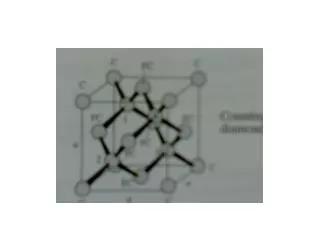
Semiconductor Lattice Structures • Diamond Lattices • The diamond-crystal lattice characterized by four covalently bonded atoms. • The lattice constant, denoted by ao, is 0.356, 0.543 and 0.565 nm for diamond, silicon, and germanium, respectively. • Nearest neighbors are spaced ( ) units apart. • Of the 18 atoms shown in the figure, only 8 belong to the volume ao3. Because the 8 corner atoms are each shared by 8 cubes, they contribute a total of 1 atom; the 6 face atoms are each shared by 2 cubes and thus contribute 3 atoms, and there are 4 atoms inside the cube. The atomic density is therefore 8/ao3, which corresponds to 17.7, 5.00, and 4.43 X 1022 cm-3, respectively. (After W. Shockley: Electrons and Holes in Semiconductors, Van Nostrand, Princeton, N.J., 1950.)
Semiconductor Lattice Structures • Diamond Lattices
Semiconductor Lattice Structures • Diamond and Zincblende Lattices Diamond lattice can be though of as an FCC structures with an extra atoms placed at a/4+b/4+c/4 from each of the FCC atoms Zincblende lattice GaAs, InP, ZnSe Diamond lattice Si, Ge The Zincblende lattice consist of a face centered cubic Bravais point lattice which contains two different atoms per lattice point. The distance between the two atoms equals one quarter of the body diagonal of the cube.
Semiconductor Lattice Structures • Diamond and Zincblende Lattices Diamond lattice Si, Ge Zincblende lattice GaAs, InP, ZnSe
Crystal Surfaces and Atomic Arrangement • Arrangement of atoms on various crystal surfaces.
Low Miller Index Planes of Cubic Lattice BCC (111) (100) (110) FCC (111) (100) (110)
Low Miller Index Planes Diamond Lattice • Diamond Lattice Structures Number of atoms per unit cell : 8 Atomic packing factor : 0.34 maximum packing density is 34 %.
Crystal Directions and Atomic Arrangement • Arrangement of atoms in Diamond lattice structures on various crystal directions.
Actual Crystal Surfaces Observed by Scanning Tunneling Microscope Silicon (100) surface Silicon (111) surface