Download
1 / 71
710 likes | 851 Vues
The Future of Accelerator Based Particle Physics. Barry Barish Czech Technical University 15-Nov-11. Path to higher energy. Collider History: Energy constantly increasing with time Hadron Collider at the energy frontier Lepton Collider for precision physics

E N D
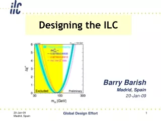
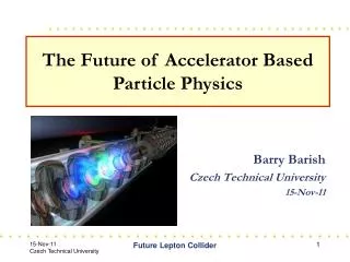
The Future of Accelerator Based Particle Physics Barry Barish Czech Technical University 15-Nov-11 Future Lepton Collider
Path to higher energy • Collider History: Energy constantly increasing with time • Hadron Collider at the energy frontier • Lepton Collider for precision physics • Consensus to build Linear Collider with Ecm > 500 GeV to complement LHC physics Future Lepton Collider
Three Generations: Complementarity First generation 3.1 GeV Burt Richter Nobel Prize and Discovery Of Charm Particles SPEAR at SLAC Future Lepton Collider 3
Rich History of Discovery Second generation DESY PETRA Collider Future Lepton Collider 4
Precision Measurements Third generation CERN’s LEP Collider set the stage for Terascale physics • Reveal the origin of quark and lepton mass • Produce dark matter in the laboratory • Test exotic theories of space and time Future Lepton Collider 5
Three Generations of Successful e+e- CollidersThe Energy Frontier 1 TeV ILC (or CLIC) LEP ENERGY PETRA Fourth generation? SPEAR 1 GeV 2020+ 1970 YEAR Future Lepton Collider 6
The next big accelerator: a lepton collider? Terascale science and how a lepton collider will complement the LHC? Electron-Positron: Why linear? What technology to employ? An option with muons? Designing the ILC -- a new paradigm in international collaboration. A thumbnail description of the ILC Reference Design and Cost? Present program and plans Future Lepton Collider 7
Exploring the TerascaleThe Tools The LHC It will lead the way and has large reach Quark-quark, quark-gluon and gluon-gluon collisions at 0.5 - 5 TeV Broadband initial state The ILC A second view with high precision Electron-positron collisions with fixed energies, adjustable between 0.1 and 1.0 TeV Well defined initial state Together, these are our tools for the Terascale Future Lepton Collider 8
Why e+e- Collisions? Elementary particles Well-defined energy angular momentum Uses full COM energy Produces particles democratically Can mostly fully reconstruct events Future Lepton Collider 9
Comparison: ILC and LHC ILC LHC Beam Particle : Electron x Positron Proton x Proton CMS Energy : 0.5 – 1 TeV 14 TeV Luminosity Goal : 2 x 1034 /cm2/sec 1 x1034 /cm2/sec Accelerator Type : Linear Circular Storage Rings Technology : Supercond. RF Supercond. Magnet Future Lepton Collider
Higgs event Simulation Comparison ILC LHC e+ e–Z H Ze+ e–, Hb … Future Lepton Collider
Higgs Signal with LHC Rare decay channel: BR~10-3 Projected signal and background after data cuts to optimize signal to background Background large: S/B 1:20, but can estimate from non signal areas CMS Future Lepton Collider 12
Precision Higgs physics • Model-independent Studies • mass • absolute branching ratios • total width • spin • top Yukawa coupling • self coupling • Precision Measurements Garcia-Abia et al Future Lepton Collider
Remember - the Higgs is a Different! • It is a zero spin particle that fills the vacuum • It couples to mass; masses and decay rates are related Higgs Coupling-mass relation Future Lepton Collider
ILC: Is it really the Higgs ? Measure the quantum numbers. The Higgs must have spin zero ! The linear collider will measure the spin of any Higgs it can produce by measuring the energy dependence from threshold Future Lepton Collider
What can we learn from the Higgs? Precision measurements of Higgs coupling Higgs Coupling strength is proportional to Mass Future Lepton Collider
e+e- : Studying the Higgsdetermine the underlying model SM 2HDM/MSSM Zivkovic et al Yamashita et al Future Lepton Collider
Supersymmetry at ILC e+e- production crosssections • - Measure quantum numbers • - Is it MSSM, NMSSM, …? • - How is it broken? • ILC can answer these questions! • tunable energy • polarized beams Future Lepton Collider
ILC Supersymmetry Two methods to obtain absolute sparticle masses: Kinematic Threshold: In the continuum Freitas Martyn Determine SUSY parameters without model assumptions Minimum and maximum determines masses of primary slepton and secondary neutralino/chargino Future Lepton Collider
The abundance of the LSP as dark matter can be precisely calculated, if the mass and particle species are given. ILC can precisely measure the mass and the coupling of the LSP The Dark Matter density in the universe and in our Galaxy can be calculated. The most attractive candidate for the dark matter is the lightest SUSY particle Dark Matter CandidatesLSP Future Lepton Collider
Linear collider Direct production from extra dimensions ? New space-time dimensions can be mapped by studying the emission of gravitons into the extra dimensions, together with a photon or jets emitted into the normal dimensions. Future Lepton Collider
Possible TeV Scale Lepton Colliders QUAD QUAD POWER EXTRACTION STRUCTURE ACCELERATING STRUCTURES BPM ILC < 1 TeV Technically possible ~ 2020 + ILC Drive beam - 95 A, 300 ns from 2.4 GeV to 240 MeV CLIC < 3 TeV Feasibility? Longer timescale CLIC Main beam – 1 A, 200 ns from 9 GeV to 1.5 TeV Muon Collider Muon Collider < 4 TeV FEASIBILITY?? Much longer timescale • Much R&D Needed • Neutrino Factory R&D + • bunch merging • much more cooling • etc Future Lepton Collider
ILC Baseline Design 250 250 Gev 250 Gev • e+ e- Linear Collider • Energy 250 Gev x 250 Gev • Length 11 + 11 km • # of RF units 560 • # of cryomodules 1680 • # of 9-cell cavities 14560 • 2 Detectors push-pull • 2e34 peak luminosity • 5 Hz rep rate, 1000 -> 6000 bunches per cycle • IP spots sizes: sx 350 – 620 nm; sy 3.5 – 9.0 nm Future Lepton Collider
RDR Design Parameters Future Lepton Collider
Linear implies single pass Circular Collider R Linear Collider cost R Synchrotron Radiation ~ 200 GeV • DE ~ (E4 /m4 R) Energy < 5 nm vertical • Low emittance (high brightness) machine optics • Contain emittance growth • Squeeze the beam as small as possible at collision point Future Lepton Collider 25
ILC – Underlying Technology Room temperature copper structures OR Superconducting RF cavities Future Lepton Collider 26
SCRF Technology Recommendation The recommendation of ITRP was presented to ILCSC & ICFA on August 19, 2004 in a joint meeting in Beijing. This recommendation is made with the understanding that we are recommending a technology, not a design. We expect the final design to be developed by a team drawn from the combined warm and cold linear collider communities, taking full advantage of the experience and expertise of both(from the Executive Summary).This led to the formation of the Global Design Effort (GDE) • ICFA unanimously endorsed the ITRP’s recommendation on August 20, 2004 • Strong international interest in developing SCRF technology Future Lepton Collider 27
GDE -- Designing a Linear Collider Superconducting RF Main Linac Future Lepton Collider 28
NC standing wave structures would have high Ohmic losses => traveling wave structures RF ‘flows’ with group velocity vG along the structureinto a load at the structure exit Condition for acceleration: Δφ=d·ω/c (Δφ cell phase difference) Shorter fill time Tfill=+1/vG dz - order <100 ns compared to ~ms for SC RF Traveling wave structures pulsed RF Power source RF load d particles “surf” the electromagnetic wave Future Lepton Collider
CLIC (Compact Linear Collider) QUAD QUAD POWER EXTRACTION STRUCTURE ACCELERATING STRUCTURES BPM Room Temperature RF Drive beam - 95 A, 300 ns from 2.4 GeV to 240 MeV Main beam – 1 A, 200 ns from 9 GeV to 1.5 TeV Future Lepton Collider
CLIC – in a nutshell CompactLinearCollider e+/e- colliderfor up to 3 TeV Luminosity 6·1034cm-2s-1 (3 TeV) Normal conductingRF accelerating structures Gradient 100 MV/m RF frequency 12 GHz Two beam acceleration principle for cost minimisation and efficiency Many common points with ILC, similar elements, but different parameters Future Lepton Collider
Structures built from discs Each cell damped by 4 radial WGs terminated by SiC RF loads Higher order modes (HOM) enter WG Long-range wakefieldsefficiently damped Accelerating structure developments Test results Future Lepton Collider
CLIC: Why 100 MV/m and 12 GHz ? after > 60 * 106 structures:100 MV/m 12 GHz chosen,previously 150 MV/m, 30 GHz A.Grudiev • Optimisation - figure of merit: • Luminosity per linac input power • Structure limits: • RF breakdown – scaling(Esurf<260MV/m , P/Cτ1/3 limited) • RF pulse heating (ΔT<56°K) • Beam dynamics: • emittance preservation – wake fields • Luminosity, bunch population,bunch spacing • efficiency – total power • take into account cost model Future Lepton Collider
Muon Collider • A muon collider is an attractive multi-TeV lepton collider option, because muons do not radiate as readily as electrons (mm / me ~ 207): • - COMPACT Fits on laboratory site • - MULTI-PASS ACCELERATION • Cost Effective operation & construction • - MULTIPASS COLLISIONS IN A RING (~1000 turns) Relaxed emittance requirements & hence relaxed tolerances- NARROW ENERGY SPREADPrecision scans, kinematic constraints • - TWO DETECTORS (2 IPs)-DTbunch ~ 10 ms … (e.g. 4 TeV collider) • Lots of time for readout Backgrounds don’t pile up • -(mm/me)2= ~40000 • Enhanced s-channel rates for Higgs-like particles A 4 TeV Muon Collider wouldfit on the Fermilab Site Future Lepton Collider
Challenges • Muons are produced as tertiary particles. To make enough of them requires a MW scale proton source & target facility. • Muons decay everything must be done fast and we must deal with the decay electrons (& neutrinos for CM energies above ~3 TeV). • Muons are born within a large phase-space. For a Muon Collider, it must be cooled by O(106) before they decay New cooling technique (ionization cooling) must be demonstrated, and it requires components with demanding performance • After cooling, beams still have relatively large emittance. Future Lepton Collider
MUON COLLIDER SCHEMATIC √s = 3 TeV Circumference = 4.5kmL = 3×1034 cm-2s-1m/bunch = 2x10¹² s(p)/p = 0.1% eN = 25 mm, e//N=70 mm b* = 5mm Rep Rate = 12Hz 1021 muons per year that fit within the acceptance of an accelerator: eN=6000 mm e//N=25 mm Proton source: Example: upgraded PROJECT X (4 MW, 2±1 ns long bunches) Future Lepton Collider
Muon Collider cf. Neutrino Factory NEUTRINOFACTORY MUONCOLLIDER In present MC baseline design, Front End is same as for NF (although the optimal initial coolers might ultimately be different) Future Lepton Collider
Muon Collider: Ionization Cooling • TRANSVERSE COOLING: Muons lose energy by in material (dE/dx). Re-accelerate in longitudinal direction reduce transverse emittance. Coulomb scattering heats beam low Z absorber. • LONGITUDINAL COOLING: Mix transverse & longitudinal degrees of freedom during cooling. Can be done in helical solenoids. • FINAL COOLING: To get the smallest achievable transverse emittance, over-cool the longitudinal emittance, and then reduce transverse emittance letting the longitudinal phase space grow. RF RF εt,,N (m) Liq. H2 Liq. H2 Liq. H2 More detail about options in R. Palmer’s talk High Field (HTS) Solenoids Future Lepton Collider
Muon Ionization Cooling Experiment (MICE) • - Tests short cooling section, in muon beam, measuring the muons before & after the cooling section. one at a time. • - Learn about cost, complexity, & engineeringissues associated with cooling channels. • Vary RF, solenoid & absorber parameters & demonstrate ability to simulate response of muons Spectro-meter Muon Beam Cooling section Spectro-meter MICE – upstream beamline Future Lepton Collider
Muon Collider Detectors • Unique to a Muon Collider are detector backgrounds from muon decay. • For TeV muon decays, the electron decay angles are O(10) mradians . Electrons typically stay inside beampipe for few meters. Hence decay electrons born within a few meters of the IP are benign. • Shielding strategy: sweep the electrons born further than ~6m from the IP into ~6m of shielding Map of backgroundparticle densities in detector Future Lepton Collider
International Linear Collider ILC Future Lepton Collider
ILC --- Deep Underground Future Lepton Collider
LHC --- Superconducting Magnet Future Lepton Collider
ILC - Superconducting RF Cryomodule Future Lepton Collider
Major R&D Goals for Technical Design Accelerator Design and Integration (AD&I) Studies of possible cost reduction designs and strategies for consideration in a re-baseline in 2010 SCRF High Gradient R&D - globally coordinated program to demonstrate gradient by 2010 with 50%yield; ATF-2 at KEK Demonstrate Fast Kicker performance and Final Focus Design Electron Cloud Mitigation – (CesrTA) Electron Cloud tests at Cornell to establish mitigation and verify one damping ring is sufficient. Future Lepton Collider Global Design Effort 45
Proposed Design changes for TDR RDR SB2009 • Single Tunnel for main linac • Move positron source to end of linac *** • Reduce number of bunches factor of two (lower power) ** • Reduce size of damping rings (3.2km) • Integrate central region • Single stage bunch compressor Future Lepton Collider
The ILC SCRF Cavity • Achieve high gradient (35MV/m); develop multiple • vendors; make cost effective, etc • Focus is on high gradient; production yields; cryogenic • losses; radiation; system performance Future Lepton Collider
Global Plan for ILC Gradient R&D New baseline gradient: Vertical acceptance: 35 MV/m average, allowing ±20% spread (28-42 MV/m) Operational: 31.5 MV/m average, allowing ±20% spread (25-38 MV/m) Global Design Effort
Cavity Gradient Milestone Achieved TDR Goal 2010 Milestone • Toward TDR goal • Field emission; mechanical polishing • Other progress Global Design Effort