Download
1 / 63
630 likes | 736 Vues
This report outlines the status, R&D progress, and future plans of the Global Design Effort for the CESRTA Wiggler project, including technical design, implementation, and beyond 2012. It covers major R&D goals for SCRF, manufacturing, testing facilities, and eCloud mitigation strategies.

E N D
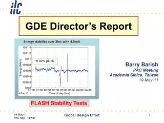
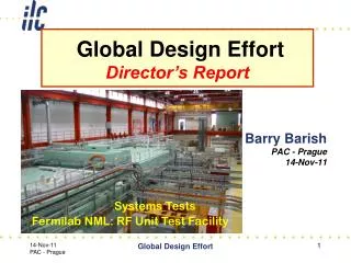
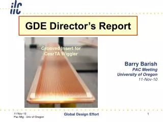
GDE Director’s Report Grooved Insert for CesrTA Wiggler Barry Barish PAC Meeting University of Oregon 11-Nov-10 Global Design Effort
Outline • Status of R&D and design • Plans through 2012 • Technical Design Report • Implementation Plan • Future beyond 2012 Global Design Effort
Our Plan --- Updated “Living” Document Global Design Effort
R & D Plan Resource Table • Resource total: 2009-2012 • Not directly included: • Other Project-specific, general infrastructure or generic R&D resources overlap with ILC R&D Global Design Effort
R&D Progress Global Design Effort
Major R&D Goals for Technical Design SCRF High Gradient R&D - globally coordinated program to demonstrate gradient by 2010 with 50%yield; improve yield to 90% by TDR (end 2012) Manufacturing: plug compatible design; industrialization, etc Future systems tests: NML (FNAL), STF2 (KEK) Test Facilities ATF2 - Fast Kicker tests and Final Focus design/performance CesrTA - Electron Cloud tests to establish damping ring parameters/design and electron cloud mitigation strategy FLASH – Study performance using ILC-like beam and cryomodule A Yamamoto for details M Ross for details Global Design Effort Global Design Effort
SCRF Status/Progress A Yamamoto for details Global Design Effort
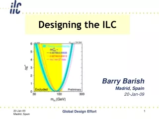
The ILC SCRF Cavity • Achieve high gradient (35MV/m); develop multiple • vendors; make cost effective, etc • Focus is on high gradient; production yields; cryogenic • losses; radiation; system performance Global Design Effort
Creation of a Global Database • Global Data Base Team formed: • Camille Ginsburg (Fermilab) • Rongli Geng (JLab) • Zack Conway (Cornell University) • Sebastian Aderhold (DESY) • Yasuchika Yamamoto (KEK) • Activities • July 2009: - Determine DESY-DB to be viable option, • Sept., 2009: (ALCPG/GDE) - Dataset, web-based, support by FNAL/DESY, • Dec., 2009: - 1st update of the yield statistics • March, 2010 - 2nd update - July, 2010 Global Design Effort
Global Plan for SRF R&D Global Design Effort
Cavity Gradient Milestone Achieved TDR Goal 2010 Milestone Global Design Effort
S1-Global Cryomodule Test in Progress DESY, FNAL, IHEP, INFN, KEK, SLAC Cooperation Vertical cavity test • CW low power test reached: < 30 MV/m > S1-Global cryomodule • 1ms, 5 Hz pulse Individual test reaching: < 28 MV/m> {as of Oct. 22, 2010} Global Design Effort
NML Cryomodule NML CM1 cryomodule (Fermilab, DESY, INFN). Closed and cool down is imminent. Global Design Effort
Test Facilities: FLASH M Ross for details Global Design Effort
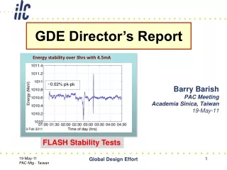
Energy stability over 8hrs(3mA, 800us bunch trains) Beam Energy J. Carwardine 2MeV (0.25%) 844 MeV Tuning change (Spec: +/-0.1%) Time (hrs) RF Vector Sums (Normalized) Nominal 0.2% Time (hrs) 8 hrs Global Design Effort 16
Test Facilities: ATF-2 M Ross for details Global Design Effort
ATF2 – Beam size/stability and kicker tests IP Shintake Monitor Final Doublet Global Design Effort
ATF2 (KEK) Status/Plans T. Tauchi Global Design Effort
Test Facilities: Cesr-TA eCloud M Ross for details Global Design Effort
eCloud R&D • Mitigating Electron Cloud • Simulations – electrodes; coating and/or grooving vacuum pipe • Demonstration at CESR critical tests Global Design Effort
Mitigation - Simulation Studies Global Design Effort
CesrTA - Wiggler Observations 0.002”radius Electrode a best performance Global Design Effort IWLC2010 - CERN, Geneva, Switzerland
CESRTA - eCloud M Palmer • Mitigation performance: • Grooves are effective in dipole/wiggler fields, but challenging to make when size is small • Amorphous C, TiN and NEG show similar levels of EC suppression so each is a potential candidate for DR use • TiN and a-C have worse dP/dI than Al chambers at our present level of processing • In regions where TiN-coated chambers are struck by wiggler radiation (high intensity and high Ec), we observe significant concentrations of N in the vacuum system • EC suppression with the clearing electrode in the wiggler is significantly better than other options • No heating issues have been observed with the wiggler design in either CESRTA or CHESS operating conditions • Work is in progress to take RFA measurements in chambers with mitigations and convert these to the effective SEY of the chamber surfaces • Agreement between data and simulation looks very promising • Magnetic field region model requires full inclusion of RFA in simulation • Trapping and build-up of the EC over multiple turns in quadrupole and wiggler chambers • Simulation and experimental evidence • Further evaluation of impact on the beam is required Global Design Effort
Design UpdateGlobal Design and Decision Making(SB2009) N Walker for details Global Design Effort
Why change from RDR design? • Timescale of ILC demands we continually update the technologies and evolve the design to be prepared to build the most forward looking machine at the time of construction. • Our next big milestone – the technical design (TDR) at end of 2012 should be as much as possible a “construction project ready” design with crucial R&D demonstrations complete and design optimised for performance to cost to risk. • Cost containment vs RDR costs is a crucial element. (Must identify costs savings that will compensate cost growth) Global Design Effort
Proposed Baseline Changes for TDR Global Design Effort
Proposed Design changes for TDR RDR SB2009 • Single Tunnel for main linac • Move positron source to end of linac *** • Reduce number of bunches factor of two (lower power) ** • Reduce size of damping rings (3.2km) • Integrate central region • Single stage bunch compressor Global Design Effort
Top Level Change Control Themes Global Design Effort
Top Level Change Control Process keywords: open, transparent Global Design Effort Global Design Effort 31 31
TLCC Process Walker Physics and detector input / representation mandatory • Baseline Assessment Workshops • Face to face meetings • Open to all stakeholders • Plenary Global Design Effort Global Design Effort 32
TLCC Process • Formal Director Approval • Change evaluation panel • Chaired by Director • Final formal step (recommended by AAP) • Change Evaluation Panel • Chaired by director • Experts to evaluate impact on performance, cost, schedule, risk • F. Asiri, K. Buesser, J. Gao, P. Garbincius, T. Himel, K. Yokoya • Decision by Director • Accepts – becomes baseline; guidance in decision memo • Rejects – sent back for further work with comments Global Design Effort Global Design Effort 33 33
Proposals Received Global Design Effort
Single TunnelHigh-Level RF Solution • Critical technical challenge for one-tunnel option is the high level RF distribution. • Two proposed solutions : • Distributed RF Source (DRFS) • Small 750kW klystrons/modulators in tunnel • One klystron per four cavities • ~1880 klystrons per linac • Challenge is cost and reliability • Klystron Cluster Scheme (KCS) • RDR-like 10 MW Klystrons/modulators on surface • Surface building & shafts every ~2 km • Challenge is novel high-powered RF components (needs R&D) • Backup: RDR-like single tunnel HLRF Global Design Effort 35
Distributed RF – Single Tunnel Global Design Effort
Klystron Cluster – Single Tunnel Global Design Effort
RDR-type RF – Single Tunnel Global Design Effort
TLCC Process Global Design Effort Global Design Effort 39
TLCC Process Global Design Effort Global Design Effort 40
Plans through 2012--------------Technical Design Report (TDR) Global Design Effort
Five Themes to Develop N Walker Remains special case Industrialisation in-kind contribution models Site requirements Project Schedule Remaining Technical activities Project Implementation Plan >2012 Global Design Effort Global Design Effort 42
Technical Design Phase and Beyond change control process AAP PAC Physics TDP Baseline Technical Design TDR RDR Baseline SB2009 evolve TDP-2 TDP-1 Beijing Workshop CERN Workshop Change Request RDR ACD concepts R&D Demonstrations AD&I studies 2009 2010 2011 2012 2013 Global Design Effort
Technical Design Phase 2 • Timescale: Produce final reports end of 2012 • Technical Design (TDR) • Project Implementation (PIP) • First goal: Technical Design (TDR) • SCRF – S0 gradient; S1 Global Tests continue past 2012 • Detailed technical design studies from new baseline • Updated VALUE estimate and schedule. • Remaining critical R&D and technology demonstration (CesrTA complete; ATF-2; FLASH; etc) • Second Goal: Project Implementation Plan (PIP) • Studies of governance; siting solicitation and site preparations; manufacturing; etc Global Design Effort
Essential Elements of TDP • Optimize the design for cost / performance / risk • Top down approach got SB2009; value engineering; risk mitigation • Key Supporting R&D Program (priorities) • High Gradient R&D - globally coordinated program to demonstrate gradient for TDR by 2010 with 90%yield • Electron Cloud Mitigation – Electron Cloud tests at Cornell to establish mitigation; determine mitigtion plan; verify one damping ring is sufficient and size. • Final Beam Optics – Tests at ATF-2 at KEK • GOAL – Bring us ready to propose a solid and defendable “construction project” to world’s governments any time after 2012 Global Design Effort
Project Implementation Plan Global Design Effort
Governance – Interim Reportpresented to FALC& ILCSC and at IWLC10 Global Design Effort
Governance – Interim Reportexample – approach to “in-kind” contributions Global Design Effort
Presently – Outline Stage Recent GDE Executive Committee Meeting during IWLC10 Global Design Effort