Mechanical Systems & Control Progression in Machinery
380 likes | 519 Vues
Learn about cams, pulleys, and gears in mechanical systems for various applications like cars, sewing machines, and toys. Discover how these components work together to transfer motion and control speed and force effectively.

Mechanical Systems & Control Progression in Machinery
E N D
Presentation Transcript
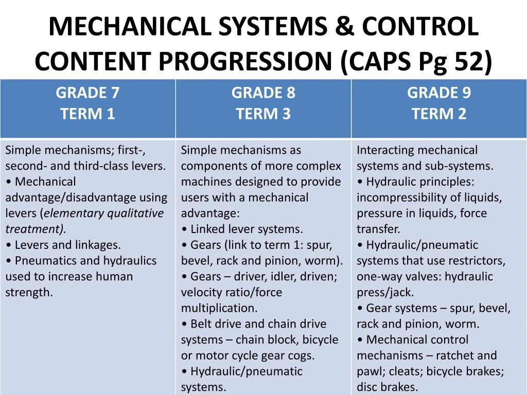
MECHANICAL SYSTEMS & CONTROL CONTENT PROGRESSION (CAPS Pg 52)
MECHANICAL SYSTEMS & CONTROL CONTENT PROGRESSION Continue......
CAMS A CAM is a simple machine in which rotary movement is changed into reciprocal movement.
CAMS Two or more Cams can be mounted to the same shaft to perform a duty. In a car engine a number ofCams are mounted to a Shaft calleda Cam Shaft. A crank which is device consisting of an arm or handle that is connected to a shaft at right angles, enabling the transmission of motion to or from the shaft is usually used to control cams. A typical application of a Cam controlled by crank in which a rotary movement is converted to a reciprocal movement is a Sewing Machine. A more complex application of Cranks and Cams shafts is an engine of a motor car.
CAMS In simpler applications, Cranks and Cams are used in the manufacturing of children’s toys.
Pulleys • A pulley is a wheel with a groove around the edge rotating freely around an axle. • A rope or belt fits into the groove which prevents it from slipping. • When using two pulleys and a flexible belt the main functions are: • To transfer rotary motion between two shafts; either in the same or opposite directions. • To make work easier or quicker when using pulleys of different sizes.
Pulleys Cont... • Pulleys can be set up in three different ways: • A single fixed pulley • A movable pulley • A combination pulley
PULLEYS Pulleys are constructed like gears as they are round but the pulleys have a groove on which the belt or rope run and gears have teeth on the outside. Pulleys operate similar to the gears except that two pulleys are joined together by the belt or rope whereas most gears mesh together with the teeth although some of the gears are joined by a chain like in a bicycle.
USES OF PULLEYS • 1. INCREASING SPEED
USES OF PULLEYS 2. DECREASING SPEED
USES OF PULLEYS 3. CHANGE DIRECTION OF ROTATION
USES OF PULLEYS 4. CHANGE THE AXIS OF ROTATION
Gears • A gear is a wheel with teeth around the edge rotating freely around an axle. • Types of gears: • Spur gear • Idler gear • Bevel gear • Worm gear • Rack and pinion
1. CHANGE THE TYPE OF MOVEMENT (Rack and pinion) Functions of gears • The first function of gears is to change the type of movement. A rack and pinion (spur • gear) changes linear motion (motion in a straight line) to circular motion (rotary • motion). The pinion is fixed on a shaft. When the pinion turns, it makes the rack move in a straight line. Pulling or pushing the rack makes the pinion turn.
2. CHANGE THE AXIS OF ROTATION AT AN ANGLE OF 90° (Bevel Gears) Functions of gears The second function of gears is to change the axis of rotation. This changes the direction of rotation through 90°. Bevel gears have sloping slides so they can be used for driving shafts that are at an angle to one another.
3. CHANGE THE DIRECTION OF MOVEMENT (Idler gear) Driven Driver Driven Driver Functions of gears Idler Driver and driven gears rotate in opposite directions. Driver and driven gears rotate in the same direction. When two gear wheels mesh, the driver gear turns in the opposite direction to the drivent gear. If a third gear is added in between, the driven gear will turn in the same direction as the driver gear. The middle gear is called the idler gear.
4. INCREASE OR DECREASE SPEED AND FORCE (Worm and gear) Functions of gears It is best to use a worm and gear wheel to obtain a large increase in force and a large decrease in speed. A small force turning the worm is turned into a large force turning the gear wheel. In this gear system motion between the shafts is transmitted at right angles similar to bevel gears.
DEMONSTRATION (20minutes) • The Changing of Gears in a bicycle to demonstrate gearing up and gearing down. (Real mountain bike used to demonstrate that when riding at a lower gear the force increases and the force decreases with an increase in the gear size.)
DEMONSTRATION (20minutes) • The use of pulleys in the car engine. (The pulley system in a car engine is demonstrated to show the increase of speed in pulley systems)
ELECTRICAL SYSTEMS AND CONTROLL PROGRESS MAP (ELCTRICAL SYSTEMS AND CONTROL)
ELECTRICAL SYSTEMS AND CONTROLL Basic electrical components
ELECTRICAL SYSTEMS AND CONTROLL Basic electrical components
ELECTRICAL SYSTEMS AND CONTROLL Basic electrical components
ELECTRICAL SYSTEMS AND CONTROLL Scenario Scenario: You stay at home with your grandmother only. She is very old and find it difficult to walk around the house during the day as she has been diagnosed with multiple illnesses that usually attack elderly people. In summer, your house is very hot and the person of her age and state of health need to stay in a normal cool room temperature. The temperature should neither be too hot no too cold as it might pose danger to her health. The problem is that during the day when you are at school there is no one to switch the fan ON and OFF for her at regular intervals to keep the room temperature constantly cool. You therefore have to design and make an electronic devise that will help you solve this problem when you are not at home. • NOTE 1: You should first build a sample working devise that will controll the light emmiting diode in the place of an electric fan. Your electronic components should be mounted on the board and placed inside an eclosure. Your enclosure can be made of cardboards or any other simple obtainerble materials. Only the LED, Thermister and the wires to the voltage supply should protrude outside the enclosure.
ELECTRICAL SYSTEMS AND CONTROLL 3D OBLIQUE SKETCH OF THE CONTROL BOX
ELECTRICAL SYSTEMS AND CONTROLL HEAT SWITCH
ELECTRICAL SYSTEMS AND CONTROLL The following circuit diagram should be used when mounting components to the board
Each group should use the Technology kit to create a models of a Crank controlling two Cams that can be used to flash Stop and Go signs when the road is under repairs. GRADE 8A CRANK AND CAM PROJECT
Each group should use the Technology kit to create the control circuit of the electric sensor. GRADE 9ELECTRICAL SENSORS
Each group should use the Technology kit to create three models of:- • 1. Fixed pulley • 2. Movable pulley • 3. Combination of three pulleys. • The same sizes of pulleys should be used and for the investigation purpose, a spring balance as well as a 500ml water bottle should be used. GRADE 8+9INVESTIGATIONS OF PULLEYS
GRADE 9ACTIVITY 2 (20minutes) • Different groups use the Technology kit to develop the models of the following:- • Group 1 Bevel Gears • Group 2 Rack and pinion • Group 3 Idler gear
ACTIVITY (COMBINATION OF SYSTEMS) Design and make a 4 wheel drive toy car that can, at a minimum, move in a straight line and in one direction only. The car should use an electric motor to move. The following materials could be used: Spur gears with an idler gear, an electric motor, a pulley with a rubber band , SPDT switch and a 6V battery at the least. Additional materials may be used.


