
APPLICATIONS
E N D
Presentation Transcript
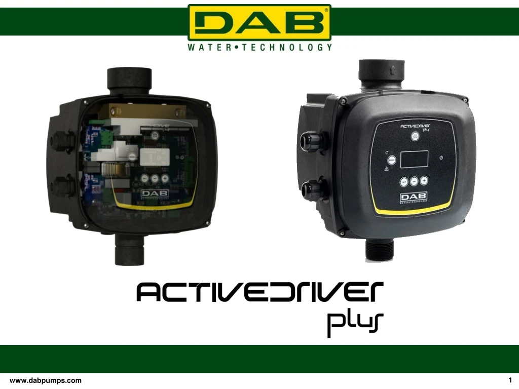
APPLICATIONS • Designed and manufactured to meet the needs for constant pressure required by modern plumbing systems, such as : • Domestic applications and light industry • Washing systems • Irrigation • Rain water utility • Well water supply (borehole pumps)
PLUS • Comfort Constant pressure • No hammering Eliminate overpressure • Easy to use Installation driven by a wizard • Easy maintenance Easy replacement flow valve • Energy saving up to 65% Environment protection : reduced CO2 • emission • Less maintenance Long life for the pump
CONSTANT PRESSURE FEATURE It’s a system that allows to have a: WITH Q = VARIABLE p = CONSTANT And thisispossiblethanks to INVERTER thatchange the frequency of alimentation of the motor
MAIN COMPONENTS This system is compose by three principal pieces: 1.Inverter 2.Flow Sensor 3.Pressure Sensor
TECHNICAL CARACTHERISTICS • VOLTAGE 50/60 HZ • INDEX OF PROTECTION IP 55 • MULTI INVERTER SYSTEMS UP TO 8 UNITS • MAXPRESSURE 13 bar • MAX FLOW 300 l/min • MAX LIQUID TEMPERATURE 50 °C • MAX ENVIRONEMENT TEMPERATURE 50 °C • INSTALLATION VERTICAL OR HORIZONTAL (ONLY M/M & M/T)
EXAMPLES OF INSTALLATION SUBMERSIBLE PUMP INSTALLATION SURFACE PUMP INSTALLATION
DIMENSIONS-COMPARISON TO THE OLD VERSION DNM 1’’ 1/2 282 / 282 237 / 211 188 / 174 DNA 1’’ 1/4
CONSTRUCTIVE CARACTHERISTICS Standard Cable gland 3 holes for inputs/outputs Integrated flow valve in Noryl Integrated pressure sensore 0-16 Bar Sensore Hall (magnetic) 1 2 3 4 5
DISPLAY INTERFACE & SOFTWARE • Software : • Multi pump booster sets up to 8 pumps • Software compatibility • Interface DISPLAY OLED - user : • Installation driven by a WIZARD • High resolution • Parameters description • ENABLE BUTTON to stop/restart the pump
PRODUCT RANGE AD M/M
PRODUCT RANGE AD M/T AD T/T
ELECTRONIC BOARD heatsink 4 Inputs, 1 input for the M/M 8,5 A version 2 outputs: status of the pump
INPUTS CLEAN CONTACT Input IN1 : pressure switch or flow switch to control the level of water reserve in the tank. Active function with input F1 JUMPER CLEAN CONTACT Input IN2 : second pressure sensor auxiliary set point Pi (P1, P2, P3), Active function with input F2 JUMPER CLEAN CONTACT Input IN3 : Enable of the inverter with an external signal + reset alarms Active function with input F3 JUMPER
OUTPUTS OUT 1 FAULT OUT 2 PUMP IS RUNNING
MULTI INVERTER SYSTEM The inverters communicate through a 3-wire connection Twisted and shielded cable Lmax between 2 inverters = 5 m Lmax between x inverters = 20 m Until8invetersconnectedtogether
EXAMPLE OF DOMESTIC BOOSTER WITH ACTIVE DRIVER PLUS MAIN COMPONENTS Protection control unit Delivery manifold Active Driver PLUS Vertical or horizontalpump Non return valve Suction manifold Metal baseplate Ball valves Vibration dampers
ENERGY SAVING Active Driver Plus supplies the water you require when it’s required. And you can see it! On the vertical axis, the time for which the pump has been on at the specific power level (% of the time with respect to the total). On the horizontal axis are the bars at the various power levels (% with respect to the maximum power). Energy Saving respect to an on-off system with the same motor power.
WINDINGS CONNECTION For the ActiveDriver M/T it is necessary change motor connection from STAR to DELTA Star Connection: Delta Connection: