Download
1 / 24
330 likes | 815 Vues
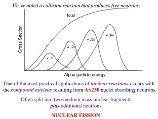
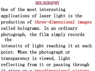
HOLOGRAPHY One of the most interesting applications of laser light is the production of three-dimensional images called holograms. In an ordinary photograph, the film simply records the intensity of light reaching it at each point. When the photograph or

E N D
HOLOGRAPHY One of the most interesting applications of laser light is the production of three-dimensional images called holograms. In an ordinary photograph, the film simply records the intensity of light reaching it at each point. When the photograph or transparency is viewed, light reflecting from it or passing through it gives us a two-dimensional picture.
Direct beam Laser light Film reflected rays Fig.1 In holography, the images are formed by Interference, without lenses. When a laser Hologram is made on film, a broadened laser Beam is split into two parts by a half-silvered mirror, Fig.1.
One part goes directly to the film; the rest passes to the object to be photographed, from which it is reflected to the film, and the interference of the two beams allows the film to record both the intensity and relative phase of the light at each point. After the film is developed, it is placed again in a laser beam and a three-dimensional image of the object is created.
Direct beam A C B D reflected rays O Fig.2 (Object) (a) Film (b) The details of how the image is formed are quite complicated. But we can get the basic idea by considering one single point on the object . In Fig.2(a), the rays OA and OB have reflected from one point on our object. The rays CA and OB come directly from the source And interfere with OA and OB at points A and B
On the film. A set of interference fringes is produced as shown in Fig.2(b). The spacing between the fringes changes from top to bottom as shown. Why this happens is explained in Fig.3. Thus the hologram of a single point object would have the pattern shown in Fig.2(b). The film in this case looks like a diffraction grating with variable spacing.
Max λ Min λ Max Min λ Max Min λ Max Min Max Fig.3 Hence, when coherent laser light is passed back through the developed film, the diffracted rays in the first-order maxima occur at slightly different angles because the spacing changes. O
Film A Laser light B Fig.4 Real image Virtual image (remember Eq. sinθ=mλ/d; so where the spacing d is greater, the angle θis smaller.) Hence, the rays diffracted upward (in first order) seem to diverge from a single point, Fig.4.
This is a virtual image of the original object, which can be seen with the eye. Rays diffracted in first order downward converge to make a real image, which can be seen and also photographed. (Noted that the straight-through undiffracted rays are of no interest.) Of course real objects consist of many points, so a hologram will be a complex
interference pattern which when laser light is incident on it, will reproduce an image of the object. Each image point will be at the correct (three-dimensional) position with respect to-other points, so the image accurately represents the original object. The image can be viewed from different angles as if viewing the original object.
THE THICK, OR VOLUME, HOLOGRAM The holograms discussed above have been assumed to have negligible thickness and are referred to as plane holograms. If the recording medium is thick with respect to the spatial frequency, the interference fringes act as a series of ribbons, somewhat similar to a Venetia blind. The reconstructing beam will generally pass through several constraint on the
diffraction pattern produced in a way similar to Bragg scattering of X rays from crystals. In the Bragg-scattering experiments, the regularly spaced atoms in the crystal act Like partially reflecting planes, scattering the waves in definite preferred directions see Fig.5. In these preferred directions the waves reflected from adjacent planes differ from each other by
53.1° 36.9° 28.1° X-ray beam 22.6° Fig.5 Exactly one wavelength and, being in phase with each other, produce constructive interference.
1 1 2 2 3 C 3 A B M Fig.6 The Bragg-scattering relationship for these directions is given byλ=2dsinθ where d is the distance between reflecting planes, λis the wavelength of the waves, and θ is the reflection angle shown in Fig.6.
MULTIPLEX HOLOGRAMS One of the remarkable features of the hologram is its ability to produce multiple scenes from the same photographic emulsion. If the distance between the fringes is smaller than the emulsion thickness, each ray of the reconstruction light originating from the direction of the reference beam will pass through several partially reflecting planes. see Fig.7.
Reillumination beam from Q hologram Fig.7 The reflection rays from each of these planes must be an integral number of wavelengths apart.
If the reillumination beam forms an angle significantly different from the reference beam, the light reflected from the adjacent planes will no longer be in phase and the virtual image will no longer be visible. It is therefore possible to produce many Holograms in the same photosensitive medium, each with the reference beam at a different angle.
When viewed later, each of these images can be separately viewed simply by varying the angle of the reference beam. This technique has been used to store hundreds of images in a single crystal of lithium niobate. The process is capable of storing an entire book in an appropriate medium by slightly changing the direction of the reference beam with each exposure.
When viewing the finished hologram, one can “turn the page” by merely moving the reconstructing beam. Alternatively, a multiplex hologram can be produced by appropriately moving the reference beam angle with time, thereby producing holographic motion picture.
H Source Q Object Fig.8 hologram H’ WHITE-LIGHT-REFLECTION HOLOGRAMS One of the possible arrangements for producing white-light holograms is to place the photosensitive film between the reference beam and the object, see Fig.8.
Such a hologram is produced simply by illuminating the object through the photosensitive medium, thus avoiding beam splitters, mirrors, etc. In practice, the reference intensity is so high relative to the scattered intensity that the technique is limited to shiny objects located close to the recording medium. Better reflection holograms can be made by separating the object and reference
Beams. Since the reference and object beams are oppositely directed, the spatial frequency is extremely high. A large number reflecting planes are thereby produced, separated by about a half wavelength of light. As a result, the reconstructing light must be of the same wavelength or the reflections from adjacent planes will not be in phase for constructive interference. Alternatively, if the hologram is
Viewed in white light, the appropriate wavelength will be selected to produce the reflected image. Ordinary photographic emulsions are of limited use as they tend to shrink during development.
OTHER HOLOGRAMS One of the most impressive holographic image is formed by a 360° circular film. The technique was developed by T.H.Jeong using a photographic emulsion mounted on a cylindrical surface surrounding the object.
HOME WORK 1. 2. 3. 4. BACK