Understanding Wireless LAN Communication Modes and Protocols
460 likes | 537 Vues
This chapter explores how clients join networks, modes of wireless LAN operation, collision avoidance methods, Request-to-Send/Clear-to-Send protocol, and effects of fragmentation.

Understanding Wireless LAN Communication Modes and Protocols
E N D
Presentation Transcript
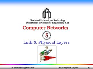
MAC & Physical Layers(1 September, 2006) Coypright 2005 All Rights Reserved
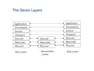
Objectives Upon completion of this chapter you will be able to: • Explain how a client joins a network • Describe the modes of operation wireless LANs use to communicate • Explain how wireless LANs avoid collisions on the network • Define the Request-to-Send / Clear-to-Send transmission protocol • Explain the effects of fragmentation on a network Coypright 2005 All Rights Reserved
Communication Modes • Wireless LANs vs. Ethernet • Joining a network • Passive scanning • Active scanning • Distributed Coordination Function (DCF) • Point Coordination Function (PCF) Coypright 2005 All Rights Reserved
IEEE 802.3 - Ethernet Coypright 2005 All Rights Reserved
PROCESS DATA DATA IEEE 802.3 DSAP CNTRL SSAP LLC-PDU PROCESS DATA 1 1 1-2 FIELD TYPE DESTINATION ADDRESS SOURCE ADDRESS LLC PDU LLC-PDU PREAMBLE ETHERNET FCS 0-1500 2 4 8 6 6 IEEE 802.3 CSMA/CD LLC PDU DA LENGTH SA LLC-PDU SFD PREAMBLE PAD FCS 0-1500 2 4 1 7 2/6 2/6 • THIS FIELD IS NOT PRESENT IN ETHERNET. • ETHERNET LENGTH MUST BE >= 64 OCTETS • THIS FIELD IS NOT IN ETHERNET. • ETHERNET HAS A TYPE FIELD • Ethernet was developed by Bob Metcalf, Xerox Corp. • Standardized in 1980 as IEEE 802.3 • CSMA/CD algorithm is same for both Ethernet and 802.3 • Frame format differs between Ethernet and 802.3 • Frame format differs between Ethernet and 802.11 Coypright 2005 All Rights Reserved
802.3 Ethernet • Frame size of 1518 bytes (1500 for payload). • Jumbo Frames are 9000 bytes • Fragmented at 1518 bytes by Host or Routers (IPv4). • 802.11 Wireless Ethernet • Frame size 2346 (3212 for payload) • Fragmented by Access Point to 1518 for traversing wired system. IEEE 802.3 FORMAT Coypright 2005 All Rights Reserved
IEEE 802.11 – Wireless Ethernet Coypright 2005 All Rights Reserved
2 2 6 6 6 2 6 0-2312 4 • Frame Duration Rec Xmit Dest Seq Src Frame FCS • Control ID Addr Addr Addr Cntl Addr Body Generic 802.11 Frame • Frame Control. Specifies control information unique to wireless transmission. • Duration. Generally indices how may microseconds the medium is expected to stay busy during transmission. • Addresses. These are the MAC address of the MS, AP and Ethernet nodes. • Sequence Field. The number of each transmitted frame. • Frame Body. The higher layer payload transmitted from station to station. • Frame Check Sequence (FCS). Used to validate the integrity of the transmitted data. Coypright 2005 All Rights Reserved
Three major 802.11 frame types exist. • Data frames carry higher level protocol data in the Frame body. • Control frames are used to assist in the delivery of data frames, administer access to the medium and to provide MAC layer reliability. • Management frames perform supervisory functions such as joining/ leaving a wireless network and move associations from AP to AP. 802.11 Frames/Protocols Coypright 2005 All Rights Reserved
Management Frames • Association Request frame • Association Response frame • Reassociation Request frame • Probe request Frame • Probe Response frame • Beacon frame • ATIM frame • Disassociation frame • Authentication frame • Deauthentication frame • Control Frames • Request to Send (RTS) • Clear to Send (CTS) • Acknowledgement (ACK) • Power-Save Poll (PS Poll) • Contention-Free End (CF End) • CF-End + CF ACK 802.11 Frame Types Coypright 2005 All Rights Reserved
CSMA/CA • The Wireless medium similar to Ethernet is a shared medium. That is, many clients attempt to access (share) the same medium. • When many clients share the same medium it is inevitable that two or more will want to transmit at the same time. • When this occurs a transmission collision occurs resulting a an error condition • In order to prevent collisions from occurring an access method is required that arbitrates who can access the shared medium • For Ethernet this is Carrier Sense Multiple Access with Collision Detection (CSMA/CD) • For 802.11 this is Carrier Sense Multiple Access with Collision Avoidance (CSMA/CA) Coypright 2005 All Rights Reserved
Carrier Sensing • Carrier sensing is used to determine if the medium is available. • 802.11 employs two types of carrier-sensing functions. • Physical Carrier Sensing. • Transceiver must receive and transmit simultaneously. • Virtual carrier Sensing Coypright 2005 All Rights Reserved
Carrier Sensing • Virtual Carrier-Sensing • Virtual Carrier Sensing is provided by Network Allocation Vector (NAV). • 802.11 frames carry a duration field which reserves the medium for a fixed time. • The NAV is a timer that indicates the amount of time the medium is to be reserved. • Stations set their NAV timer upon receipt of a frame containing a duration field. • Stations cannot transmit during that period. • When the NAV timer reaches zero the Virtual Carrier-Sensing indicates the medium is idle and the station can transmit. • For the station to transmit both the physical and virtual carrier sense must report an idle condition otherwise the station must enter a deferral condition. • If the station can transmit it must observe Interframe spacing (IFS) Coypright 2005 All Rights Reserved
Interframe Spacing Coypright 2005 All Rights Reserved
Interframe Spacing • Interframe Spacing (IFS) ensures the medium is idle for a minimum period of time prior to transmission. • IFS Serves two primary functions. • First, IFS ensures that all frames are spaced in time such that they will be received as distinct frames. • Secondly, it provides a priority access mechanism whereby certain types of frames are able to preempt other frames. • Priority access is provided to frames by allowing them to be preceded by shorter interframe spacing. • There are four main lengths of interframe spacing. • Short Interframe Spacing (SIFS) • Point Coordination Function (PCF) Interframe Spacing (PIFS) • Extended Interframe Spacing (EIFS) • Distributed Coordination Function (DCF) Interframe Spacing (DIFS) Coypright 2005 All Rights Reserved
Interframe Spacing • There are four different types of interframe spacing. • Short Interframe Space (SIFS). • SIFS is used for high priority traffic such as RTS/CTS and ACK. • Higher priority traffic begins immediately after the expiration of SIFS. • SIFS is normally used at the following times: • To send an ACK in response to a data frame. • To send a CTS in response to an RTS frame. • To send a data frame following a CTS frame. • To send all other fragments following the first fragment. • All frames exchanged during the PCF mode. Coypright 2005 All Rights Reserved
Interframe Spacing • There are four different types of interframe spacing. • PCF Interframe Space (PIFS) • PIFS is used by PCF during contention-free operation. • Access points only use PIFS when the network is in PCF mode which must be manually configured by the administrator. • The PCF mode allows the AP to control which stations may transmit. • No known vendor implements PCF. • PIFS only works with DCF (BSS, ESS, IBSS) and not Ad-hoc mode. • Extended Interframe Space (EIFS). • EIFS is used when there is an error in transmission and has no fixed interval. Coypright 2005 All Rights Reserved
Interframe Spacing • There are four different types of interframe spacing. • DCF Interframe Space (DIFS) • DIFS is used for contention based services and is the default interframe space on all 802.11 stations. • Each station in DCF mode waits until DIFS has expired before contending for the network. • DCF transmission have lower priority than PCF based transmissions. • A contention period immediately follows the DIFS Coypright 2005 All Rights Reserved
Interframe Spacing contd • IFS DSSS FHSS infrared • SIFS 10 uS 28 uS 7 uS • PIFS 30 us 78 uS 15 uS • DIFS 50 uS 128 uS 23 uS Coypright 2005 All Rights Reserved
Interframe Spacing Relationship Contention Window • DIFS • PIFS • Frame Transmission • SIFS • Busy Coypright 2005 All Rights Reserved
Contention Window Coypright 2005 All Rights Reserved
Contention Window • The interframe spacing time is followed by a contention window. • During the contention window all stations desiring to transmit data chooses random backoff time (time to wait). • Each station uses a random back off algorithm to determine how long to wait before transmitting. • A contention period (CP) immediately follows the (DIFS). • The station chooses a random number and multiplies it by the slot time to get a length of time to wait. • The station performs a Clear Channel Assessment (CCA) after each time slot to see if the medium is busy. • The station can transmit provided: • (1) the medium is clear and • (2) the NAV is zero Coypright 2005 All Rights Reserved
Slot Times • The slot time multiplied by the random number to obtain the wait time is dependent upon the particular physical layer (DSSS, FHSS, OFDM ,etc) • Slot Times • FHSS 50 uS • DSSS 20 us • Infrared 8 uS • PIFS = SIFS + 1 Slot Time • DIFS = PIFS + 1 slot Time Coypright 2005 All Rights Reserved
The Contention Window • Contention Window = 31 Slots • 802.11b • Initial • Frame • DIFS • Contention Window = 63 Slots • 1st Retrans • Frame • DIFS • Contention Window = 127 Slots • 2nd Retrans • Frame • DIFS • The Contention Window is divided into time slots. • The length of each slot is medium dependent. • Stations pick a random slot and wait for that time slot before attempting to access the medium. • The station with the lowest random number (slot) accesses first. • The number of slots will always be 1 less than the power of 2. • 25-1, 26-1, 27-1, etc Coypright 2005 All Rights Reserved
Station Backoff with DCF • Stations contend to transmit after expiration of the DIFS. • The Contention Window (Backoff Window) follows the DIFS. • The CW is divided into slots with the slot length depending upon the medium, e.g., DSSS = 20 uS. • The station chooses a random number and multiplies it by the slot time to get a length of time to wait. • The station counts down the slot times until its slot arrives. • Each time transmission fails (stations picked the same time slot) the backoff time is selected from a larger range. • 25-1 = 31, 26-1=63, etc., timeslots Coypright 2005 All Rights Reserved
DSSS Contention Window Size (802.11b) Coypright 2005 All Rights Reserved
CSMA/CA • Carrier Sense Multiple Access w/ Collision Avoidance (CSMA/CA). • Listen Before Talking (LBT). • CSMA/CA avoids collisions and uses positive acknowledgements (ACKs) instead of arbitrating the use of the medium such as CSMA/CD. • An ACK is require for each frame sent. If no ACK is received it is assumed that the frame was not received. • Collision avoidance is implemented through two distinct coordination functions. • Distributed Control Function (DCF) defines how stations contend for the wireless medium (contention based). • Point Control function (PCF) defines how the wireless medium is used during contention-free access. Coypright 2005 All Rights Reserved
Coordination Function • Distributed CoordinationFunction (DCF) defines how stations contend for the wireless medium (contention based access). • DCF is the implementation of CSMA/CA and encompasses such things as IFS, CCA, Contention window, etc. • DCF refers to the fact that the transmission coordination of each station is distributed among all stations. • Point Control function (PCF) defines how the wireless medium is used during contention-free access. • PCF refers to the fact that the AP acts as a central point to control (manage) when each station will transmit. • The AP does this by polling each station. • No AP is known to implement this function Coypright 2005 All Rights Reserved
802.11e • - QoS- Coypright 2005 All Rights Reserved
802.11e Background • 802.11 is increasingly being used for multimedia streaming functions such as voice and video. • These applications are sensitive to time deviation in the processing of packet at the receiver. • Time deviations in the arrival of packets resulted in jerky motion or garbled sound. • The Point Coordination Function PCF) mode was intended to guarantee regular access to the medium and to accommodate VoIP and streaming multimedia. • Few if any vendors implemented PCF. • In addition, PCF was not designed to give priority to different application coming from the same MAC address. Coypright 2005 All Rights Reserved
802.11e • To address the limitation of 802.11 associated with streaming multimedia IEEE introduced 802.11e. • 802.11e defines a Quality of Service (QoS) extension to the 802.11 MAC layer designed to accommodate streaming multimedia. • QoS (Quality of Service) is the idea that transmission rates, error rates, and other characteristics can be measured, improved, and, to some extent, guaranteed in advance. • QoS provides subscribers better reception for full-motion video, high-fidelity audio, and Voice over IP through the Internet. • 802.11e modifies the rules associated with DCF and PCF to create, respectively: • an Enhanced Distributed Channel Access Function (EDCAF) for DCF or DCF plus QoS • And a Hybrid Coordination Function (HCF) or PCF plus QoS Coypright 2005 All Rights Reserved
EDCAF • EDCAF defines 8 traffic priority levels with the higher priority traffic being transmitted first. • EDCAF does not provide any guaranteed bandwidth but it does provide an increased probability that stations with high priority traffic will transmit first. • An Arbitration Interframe Space (AIFS) wait period which corresponds to the traffic priority is transmitted prior to the data. • The stations with the highest priority traffic which corresponds to the smallest AIFS wait period, transmits data. Coypright 2005 All Rights Reserved
HCF • The Hybrid Coordination Function (HCF) polls stations during contention-free periods and grants each station a specific start time and maximum duration for transmission. • During the Contention Free Period (CFP), the AP (Hybrid Coordinator) controls the access to the medium. • The HCF defines a number of different Traffic Classes (TC). • The stations give information about the lengths of their queues for each Traffic Class (TC) to the AP. • The AP uses this information to give priority to one station over another. • In addition, stations can be given a Transmit Opportunity (TXOP) and, for a given time period selected by the HC, they may send multiple packets in a row. • Since PCF has not been widely used, this second enhancement has received lower interest levels than Enhanced DCF, although the two can work together. Coypright 2005 All Rights Reserved
RTS/CTS Coypright 2005 All Rights Reserved
Carrier Sensing Review • CSMA/CA is based upon two types of carrier sensing mechanisms • Physical Carrier and • Virtual Carrier-Sensing • Virtual Carrier Sensing is provided by Network Allocation Vector (NAV). • 802.11 frames carry a duration field which reserves the medium for a fixed time. • The NAV is a timer that indicates the amount of time the medium is to be reserved. • Stations set their NAV timer upon receipt of a frame containing a duration field. • Stations cannot transmit during that period. • When the NAV timer reaches zero the Virtual Carrier-Sensing indicates the medium is idle and the station can transmit. • For the station to transmit both the physical and virtual carrier sense must report an idle condition otherwise the station must enter a deferral condition. Coypright 2005 All Rights Reserved
Carrier Sensing Review Contd • For the station to transmit both the physical and virtual carrier sense must report an idle condition otherwise the station must enter a deferral condition. • Each data frame contains a duration field that sets the NAV timer in all stations. • This value is long enough to (1) transmit an ACK in response to a data frame and to (2) account for the IFS. • The NAV value is said to protect the ACK • If an RF coverage area has a high rate of collisions, CSMA/CA, based upon carrier sensing, will not help the problem of collission. • Under these circumstances it might be more efficient to reserve transmission time. • This reservation of transmission time is the purpose of RTS/CTS Coypright 2005 All Rights Reserved
RTS/CTS • The client station issue a Request to Send (RTS) frame to the AP. This frame contain a duration field value which is issued to set the NAV timer. • All stations in the BSS will hopefully hear the RTS. Some may not due to the Hidden Node problem. • The AP responds with a Clear to Send (CTS) frame which contains a shorter Duration field because all stations may not have heard the RTS –remember the hidden Node problem. • All stations in the BSS now set their NAV timer and will not attempt to transmit unit their NAV timer decreases to zero. • The client then passes data to the AP which ACKs the data transmission. • After this exchange the wireless medium may be used by any station after the Distributed Interframe Space (DIFS). Coypright 2005 All Rights Reserved
RTS/CTS Handshaking The RTS/CTS contains a Duration value which sets the NAV timer Coypright 2005 All Rights Reserved
RTS/CTS Process Station Access Point • SIFS - Short Interface Frame Space • DIFS - Distributed Interface Frame • A client transmits an RTS frame to the AP. • The receiving AP respond with a CTS frame containing a shorter duration field. This value is used to set the NAV timer by the other stations. • After this exchange all clients in the BSS then contend based upon the contention window after the DIFS. Coypright 2005 All Rights Reserved
RTS/CTS Issues • RTS/CTS causes significant overheard traffic on the WLAN thereby reducing throughput. • Because it decreases throughput RTS/CTS is normally turned OFF by default on a WLAN. • Most vendor products will allow the Wireless Network Administrator to set the RTS/CTS threshold if required. • If the network is experiencing a high amount of collisions this may indicate a Hidden Node. • One solution to a high collision rate may be RTS/CTS. Coypright 2005 All Rights Reserved
Fragmentation • and • Reassembly Coypright 2005 All Rights Reserved
Fragmentation and Reassembly • Fragmentation, breaking larger packets into smaller size packets, is a techniques used in wireless communication to improve the throughput of the wireless channel as a result of interference caused by microwave ovens, wireless phones, jamming, etc., • Interference affects smaller fragments less than larger fragments. • Fragments all have the same sequence number but ascending fragment numbers to aid in reassembly. • Frame control information indicates whether more fragments are coming. • Stations never fragment multicast or broadcast frames. Coypright 2005 All Rights Reserved
Fragmentation • There is a tradeoff between the lower frame error rate that can be achieved by fragmentation and the increase overhead due to fragmentation • Fragments comprising a frame are normally sent in fragmentation bursts. Coypright 2005 All Rights Reserved
Fragmentation Burst • Fragments and their ACKs are separated by SIFS so a station retains control of the channel during the fragmentation burst. • The NAV is used to retain control of the channel. • The RTS/CTS set the NAV from the expected time to the end of the first fragment. • The ACK fragments set the NAV thereafter until completion of the fragmentation burst. Coypright 2005 All Rights Reserved
End of Lecture Coypright 2005 All Rights Reserved