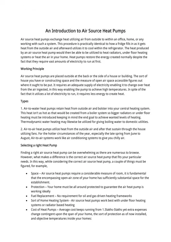
Air-Source Heat Pumps
1.27k likes | 2.59k Vues
Air-Source Heat Pumps. North Seattle Community College HVAC Program Instructor – Mark T. Weber, M.Ed. Airsource Heat Pump 1. Reverse-Cycle Refrigeration. Air-conditioning equipment can only pump heat in one direction Heat pumps can pump heat two ways Also have a four-way reversing valve

Air-Source Heat Pumps
E N D
Presentation Transcript
Air-Source Heat Pumps North Seattle Community College HVAC Program Instructor – Mark T. Weber, M.Ed. Airsource Heat Pump 1
Reverse-Cycle Refrigeration • Air-conditioning equipment can only pump heat in one direction • Heat pumps can pump heat two ways • Also have a four-way reversing valve • Four-way reversing valves control the direction of flow of the heat-laden vapor between the low- and high-pressure sides of the system
Heat Sources For Winter • Air conditioners pump heat from low temperature inside the structure to a higher temperature outside the house • At 0°F outside air temperature, there is still 85% usable heat in the air • The heat pump removes heat from the outside air in the winter and deposits it in the conditioned space to heat it
Heat Sources For Winter (cont’d.) An air-to-air heat pump removing heat from 0°F air and depositing it in a structure for winter heat
The Four-Way Valve • Allows the heat pump to pump heat in two directions • Diverts the discharge gas to either heat or cool the conditioned space • Refrigerant is directed from the compressor to the indoor coil in the heating mode
The Four-Way Valve (cont’d.) • Refrigerant is directed from the compressor to the outdoor unit in the cooling mode • Controlled by the space temperature thermostat • Pilot-operated valve • Four piping connections on the valve
The Four-Way Valve (cont’d.) An air-to-air heat pump moving heat from the inside of a structure to the outside
The Four-Way Valve (cont’d.) In the winter, the heat pump moves heat into the structure
The Four-Way Valve (cont’d.) Internal slide in the four-way reversing valve. The solenoid determines the position of the slide. Most systems operate in the heating mode when the solenoid is deenergized. (A) Position of the slide when the solenoid is deenergized. (B) Position of the slide when the solenoid is energized
Types of Heat Pumps • Air is not the only source from which a heat pump can absorb heat • Other heat sources for heat pumps include water and earth • A typical water-to-air heat pump uses 3 gallons of water per minute in the heating cycle and 1.5 gallons of water per minute in the cooling mode per ton of refrigeration
The Air-to-Air Heat Pump • Most popular type • Basic sealed system components of a heat pump are the same as an air conditioner, but the terminology changes • In a heat pump, the terms indoor coil and outdoor coil are used • The function of each coil changes as the operating mode of the heat pump changes
The Air-to-Air Heat Pump (cont’d.) • Function of coils in the heating mode • Outdoor coil absorbs heat by boiling refrigerant at low temperature and pressure (evaporator) • Indoor coil rejects heat by condensing it to a high-temperature and pressure vapor (condenser) • Hot gas from the compressor is first pumped to the indoor coil
In the heating mode, the high-pressure hot gas from the compressor is directed to push the main valve’s slide to the left. This directs the hot gas from the compressor to the indoor coil to provide space heating. Notice that the solenoid is deenergized
The Air-to-Air Heat Pump (cont’d.) • Function of coils in the cooling mode • Indoor coil absorbs heat by boiling refrigerant at low temperature and pressure (evaporator) • Outdoor coil rejects heat by condensing it to a high-temperature and pressure vapor (condenser) • Refrigerant from the compressor is first pumped to the outdoor coil
In the cooling mode, the high-pressure hot gas from the compressor is directed to push the main valve’s slide to the right. This directs the hot gas from the compressor to the outdoor coil. Notice that the solenoid is energized
The Air-to-Air Heat Pump (cont’d.) • Mode of operation is determined by which way the hot gas from the compressor is flowing • Mode of operation can be determined by touching the gas line to the indoor coil • In the cooling mode, the gas line will feel cool • In the heating mode, the gas line will feel hot
Refrigerant Line Identification • The larger diameter line is called the gas line because only refrigerant vapor flows through it • The gas line is a cold gas line in the summer and a hot gas line in the winter
Refrigerant Line Identification (cont’d.) • The smaller diameter line is called the liquid line because only liquid refrigerant travels through it • During the cooling mode, the liquid travels to the indoor coil • During the heating mode, the liquid travels to the outdoor coil
Refrigerant Line Identification (cont’d.) This split-system heat pump shows the interconnecting refrigerant lines
Metering Devices • Specially designed for heat pump applications • There must be a metering device at the outdoor unit in the heating mode • There must be a metering device at the indoor coil in the cooling mode
Thermostatic Expansion Valves • Maintains desired superheat in the evaporator • Check valves are piped parallel to the TXV to allow refrigerant to bypass the control when needed
Thermostatic Expansion Valves (cont’d.) • Heating mode • The refrigerant flows through the TXV at the outdoor coil • The refrigerant bypasses the TXV at the indoor coil
Thermostatic Expansion Valves (cont’d.) • Cooling mode • The refrigerant flows through the TXV at the indoor coil • The refrigerant bypasses the TXV at the outdoor coil
Thermostatic Expansion Valves (cont’d.) In the heating mode, hot gas from the compressor flows through the indoor coil and through the open check valve to bypass the indoor metering device.(B) In the cooling mode, high-pressure liquid refrigerant is directed through the metering device because the check valve will be in the closed position
The Capillary Tube • Commonly used on heat pumps • Will allow refrigerant to flow both ways • Sometimes two capillary tubes are used with check valves • There must be a drier/strainer at the inlet of the capillary tube to ensure that the tube does not get clogged
Combinations of Metering Devices • Uses the capillary tube at the indoor coil • Used in the cooling mode • Load is relatively constant in the warmer months • Uses a thermostatic expansion valve at the outdoor coil • Used in the heating mode • Allows system to reach maximum efficiency quickly
Electronic Expansion Devices • Can meter refrigerant in both directions • If indoor and outdoor coils are close together, one device can be used • The correct superheat will be maintained in both heating and cooling modes
Orifice Metering Devices • Used in conjunction with check valves • One device is located at each coil • The bore at the indoor coil is larger than the bore at the outdoor coil • Normally used with a bi-flow filter drier
Liquid Line Accessories • Two standard filter driers can be used on systems with check valves • Only one drier in the circuit at a time • They are installed with the arrows pointing in the same direction as the check valves • Bi-flow filter driers • Two driers in one • Designed for heat pump applications
Liquid Line Accessories (cont’d.) In the heating mode, the cooling metering device is bypassed
Liquid Line Accessories (cont’d.) In the cooling mode, the heating metering device is bypassed
Application of the Air-to-Air Heat Pump • Usually installed in milder climates • In winter, the outdoor coil absorbs heat • If outside temperature is 10° • Refrigerant boils at approximately -15° • Compressor and the system lose efficiency as the evaporator temperature drops • The system loses capacity as the outside temperature drops
Auxiliary Heat • Required when the heat pump cannot provide all the heat a structure needs • The heat pump is the primary heat source • Auxiliary heat could be electric, oil or gas • Electric heat is the most common auxiliary heat used • As the outside temperature drops, the structure requires more heat
Balance Point • Balance point occurs when the heat pump can pump in exactly as much heat as the structure is leaking out • Above the balance point, the heat pump will cycle on and off • Below the balance point, the heat pump will run continuously and second stage (auxiliary) heat will be energized
Coefficient of Performance • One watt of usable heat is supplied for each watt of energy purchased • 100% efficient • Coefficient of performance (COP) of 1:1 • The output is the same as the input • Air-to-air heat pumps: a COP of 3.5:1 • One watt of electrical energy used by the compressor can furnish 3.5 watts of usable heat
Coefficient of Performance (cont’d.) • High COP only occurs during higher outdoor winter temperatures • A heat pump’s COP falls as the outdoor temperature falls • A typical air-to-air heat pump has a COP of 1.5:1 at 0°F
Coefficient of Performance (cont’d.) • Some manufacturers have controls to shut off the compressor at temperatures of 0 to 10°F • Water-to-air heat pumps might not need auxiliary heat since the heat source (water) temperature is constant • Water-to-air heat pumps have a COP rating as high as 4:1
Split-System Air-to-Air Heat Pumps • Air-to-air systems can be split or package type • Both heat pumps and straight cooling units look identical • Split systems require the installation of the gas and liquid refrigerant lines to connect the indoor and outdoor units
The Indoor Unit • The part of the system that circulates the air within the structure • Contains the fan and coil and often the electric strip heaters • The refrigerant coil must be located in the airstream before the auxiliary heating coil • The indoor unit may be a gas or oil fired furnace
The Indoor Unit (cont’d.) • If gas or oil furnace is the indoor unit, the coil must be located in the outlet airstream of the furnace • If a gas or oil furnace is used, the heat pump will not operate while they run • Heat pumps added to electric furnaces should have the coil located after the heat strips
Air Temperature of the Conditioned Air • Air temperatures of a heat pump are not as hot as with fossil-fuel equipment • Maximum heat pump air supply temperatures are around 100°F • Most heat pumps require a minimum of 400 cfm per ton of refrigeration • Supply air temperature will fall when outside air temperatures drop
The Outdoor Unit Installation • Must have good air circulation around it • Prevailing winds affect performance • In the wintertime, the outdoor coil will collect moisture that freezes • Outdoor coil should be installed so it is raised above the ground pad to allow defrost water to run to the ground • A defrost system defrosts the ice from the outdoor coil
Air Temperature of the Conditioned Air (cont’d.) This air distribution system with the air being distributed from the inside using high sidewall registers shows the heat pump’s 100°F air mixing with the room air of 75°F This heat pump installation shows a good method of distributing the warm air in the heating mode
Package Air-to-Air Heat Pumps • Has all the sealed system and electrical components in one housing • Works much the same way as a packaged air-conditioning unit • Only one power supply required • Supply and return ductwork must be field-installed
Package Air-to-Air Heat Pumps (cont’d.) The self-contained unit contains the outdoor coil and the indoor coil. The ductwork must be routed to the unit
Controls for Air-to-Air Heat Pumps • Controls are different than other heating/cooling equipment • In a heat pump, there are two heating systems and one cooling system • Auxiliary heating system must be operated as a system by itself in case the heat pump fails
Controls for Air-to-Air Heat Pumps (cont’d.) • Auxiliary heat is referred to as emergency heat when used because of heat pump failure • The space thermostat is the key to controlling the system • Normally, a two-stage heating and two-stage cooling thermostat is used
Controls for Air-to-Air Heat Pumps (cont’d.) • Automatic changeover thermostat • Changes between heating/cooling modes • Cooling cycle controls • Thermostat contacts control the operation of the compressor, outdoor fan motor, & reversing valve coil • When the thermostat is satisfied, the compressor, outdoor fan motor, and indoor fan motor are de-energized, but the reversing valve solenoid coil remains energized
Controls for Air-to-Air Heat Pumps (cont’d.) The first stage of the cooling cycle in which the four-way valve magnetic holding coil is energized
Controls for Air-to-Air Heat Pumps (cont’d.) Figure 43-42 This diagram shows what happens with a rise in temperature. The first stage of the thermostat is already closed; then the second stage closes and starts the compressor. The compressor was the last on and will be the first off