Download
1 / 10
100 likes | 123 Vues
Explore the latest developments in the SAM chip technology for ultra-fast time measurements. Discover the advancements in USB-powered 12-bit digitizers and their potential applications. Follow the progress in achieving picosecond resolution and reducing jitter for enhanced accuracy in various scientific experiments. Learn about upcoming innovations and collaborations in the field.

E N D
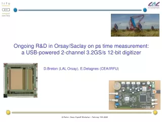
Ongoing R&D in Orsay/Saclay on ps time measurement: a USB-powered 2-channel 3.2GS/s 12-bit digitizerD.Breton (LAL Orsay), E.Delagnes (CEA/IRFU) Séminaire DRT/LIST 08/09/08 SACLAY.
The SAM (Swift Analog Memory) chip • 2 differential channels • 256 cells/channel • BW > 450 MHz • Sampling Freq 400MHz->3.2GHz • High Readout Speed > 16 MHz • Smart Read pointer (integrates a 1/Fs step TDC) • Few external signals • Many modes configurable by a serial link. • Auto-configuration @ power on • AMS 0.35 µm => low cost for medium size prod NIM A, Volume 567, Issue 1, p. 21-26, 2006 6000 ASICs manufactured, tested and delivered in Q2 2007
Principle of the SAMPLING MATRIX 1 amplifier/line Short DLL: less jitter Parallelized Readout Individual delay servo-control / column: stability
The SAM-USB board Reference clock. Up to 200MHz => 3.2GS/s Power consumption < 2.5W Pulsers for reflectometry applications 1 GHz BW amplifier. 2 analog inputs. DC coupled µ USB Ext clk & Trigger inputs Dual 12-bit ADC SAM Chip Trigger comparators
Test results: short pulse sampling 1ns FWHM pulse sampled @ 3.2GS/s (75mV) [mV] single shot 300ps/cell
Fixed pattern jitter • DNL => modulo 16 pattern. Time step spread = 6.6 ps rms • INL => modulo 16 pattern + slow pattern. • “Absolute time” spread = 23 ps rms (100 ps peak-peak) • Seems to be the major part of the jitter. • Position correlated => could be corrected (off-chip) => TO BE DONE • Advantage of servo-controlled structure: very small dependence to time and temperature
Random jitter • With random trigger: jitter floor ~ 2.5 ps rms but with larger jitter on “transition” samples (16 ps). Mean jitter ~ 5 ps • Understood: due to the clock jitter which can be seen only on the last cell of the DLLs • Source is unknown yet: could be the board (FPGA) or the chip • Next board will have a direct connection between oscillator and SAM to farther study this problem.
Recording of a MCPPMT pulse in Jerry’s lab ~ -1V 1.25 ns / div • Unfortunately, the board was equipped with a 100 MHz oscillator => the wave was sampled at only 1.6 GHz!
R&D on a ps TDC in IBM 130nm technology • We are collaborating to the design of a new TDC in the IBM 130nm technology • This is a collaboration between Orsay, Saclay, and the University of Chicago (with the help of Gary Varner). • The goal is to reach the ps precision thanks to the addition to an usual DLL based TDC of analog memories sampling at very high frequency (10 to 40GS/s). • Input clock frequency should be 312.5 MHz • We started designing the first prototype • main characteristics are almost fixed now • It should include a complete measurement channel • In the near future, we aim at building a 16-channel chip with integrated output buffers. • These chips will be used at the output of fast PMT’s • We already have a SiPM test bench here at LAL driven by the “instrumentation” group • This bench will soon be extended to MCPPMT’s • An ANR file has been filed in November for this R&D. It covers both the electronics, detectors and photo-detectors aspects.
Conclusion • We built a USB board to push the SAM chip towards its limits. • Timing measurements showed a timing resolution of ~25 ps rms without any off-chip correction. • Timing resolution with correction and using several samples is under study. • Very small random jitter (few ps), mainly due to clock jitter => work was done to optimize the board performances. • Tests gave us new guidelines for future chips to improve timing performances. • We are now convinced that a single chip can’t be optimum for all applications (long depth vs time precision). • Next circuit will be submitted soon: 5GS/s sampling freq, larger BW (700MHz ?), same techno (0.35µm), larger depth (1024 pts/ch) => target = precision time measurement • Upgraded version of the SAM-USB board will be available within the next days. • Can be used for low cost fast detector testing (already compatible with next circuit). • Will be tested with MCPPMT’s. • More details and results about this in my talk in the electronics session tonight. • A new ps TDC is under design.