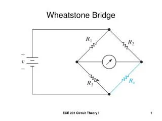
The Wheatstone Bridge
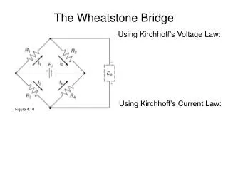
Combining the above gives the Wheatstone Bridge (WB) equation:. The Wheatstone Bridge. Using Kirchhoff’s Voltage Law:. red loop: E i = I 1 R 1 + I 2 R 2. green loop: E i = I 3 R 3 + I 4 R 4. blue loop: E o = I 4 R 4 - I 2 R 2. gold loop: E o = -I 3 R 3 + I 1 R 1.

The Wheatstone Bridge
E N D
Presentation Transcript
Combining the above gives the Wheatstone Bridge (WB) equation: The Wheatstone Bridge Using Kirchhoff’s Voltage Law: red loop: Ei = I1R1 + I2R2 green loop: Ei = I3R3 + I4R4 blue loop: Eo = I4R4 - I2R2 gold loop: Eo = -I3R3 + I1R1 Using Kirchhoff’s Current Law: Figure 4.10 I1 = I2 (at top node) I3 = I4 (at bottom node).
Rx • What is the Wheatstone • bridge equation if another • resistor, Rx, is added in • parallel with R1 ? • 1/Rnew = 1/Rx+1/R1 • To solve, simply substitute • Rnew = R1Rx / (R1+Rx) • into the original WB equation for R1.
Rx FLOW • One advantage of using two resistors in parallel in • one leg of the WB is that the added resistor can be • located remotely from the actual WB, such as in a flow. • Here, that resistor can serve as a sensor.
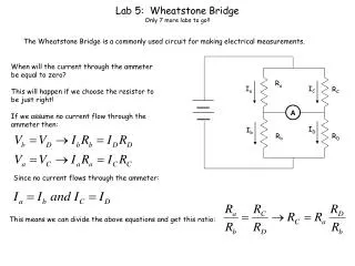
→ • When Eo = 0, the WB is said to be ‘balanced’ → • When the WB is balanced and 3 of the 4 resistances • are known, the 4th (unknown) resistance can be found • using the balanced WB equation. The is called the null • method.
Now consider the case when all 4 resistors are the • same initially and, then, one resistance, say R1, is changed • by an amount dR. This is called the deflection method. • Often, dR is associated with a change in a physical variable.
In-Class Example Figure 4.18 RTD: aRTD = 0.0005 / ºC; R = 25 W at 20.0 ºC Wheatstone Bridge: R2 = R3 = R4 = 25 W; Ei =5 V Amplifier: Gain = G Multimeter: 0 V to 10 V range (DC) Experimental Operating Range: 20 ºC to 80 ºC
Cantilever Beam with Four Strain Gages • From solid mechanics, for a cantilever beam, both the elongational strain, eL, and the compressive strain, eC, are directly proportional to the applied force, F. Figure 4.11 Figure 6.2 • When F is applied as shown (downward), R1 and R4 • increase by dR (due to elongation), and R2 and R3 • decrease by dR (due to compression). Here, dR is directly proportional to the strains.
The Cantilever Beam with Four Gages • The WB equation becomes which reduces to Eo = Ei (dR/R). • Because dR ~ (eL or eC) and (eL or eC) ~ F, Eo = constant x F • This instrumented cantilever beam system is the basis for many force measurement systems (like force balances and load cells.