Download
1 / 49
550 likes | 859 Vues
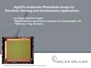
Physics and applications of HgCdTe APDs. Ian Baker (SELEX) and Johan Rothman (CEA LETI) 09/10/2013. Outline. Amplified photodetection HgCdTe APDs physics and limitations HgCdTe APD HgCdTe APD applications with arrays (imagery) and single pixel detectors Summary/perspectives.

E N D
Physics and applications of HgCdTe APDs Ian Baker (SELEX) and Johan Rothman (CEA LETI) 09/10/2013
Outline • Amplified photodetection • HgCdTe APDs physics and limitations • HgCdTe APD • HgCdTe APD applications with arrays (imagery) and single pixel detectors • Summary/perspectives
Photodetection without internal gain Photon signal Readout noise sRO Measured signal
Photodetection with gain M M x Photon signal Internal photodetector gain M RO noise M Measured signal The gain extracts the signal from the read-out nosie: Low signals and/or high read-out noise : 0.001- 10 000 photons per observation time
Photodetector gain Amplifies the signal to avoid SNR degradation due to the noise in the read-out electronics Avoid loosing information … at best: P(M) sM M <M> PD gain Excess noise factor Information conservation FM
MxSignal+ Read out noise (Noise floor) Avalanche gain with low excess noise 100mV Signal x QE Signal (100 photons) 10mV High F Amplified SNR Low F Variance in gain multiplies photon noise x√F (F=APD excess Noise Factor) 1mV ~Photon SNR Output voltage Photon noise (10 x√QE) 100µV Electronic noise floor (FN) 10µV Darkcurrent noise 1µV Increasing Gain The object of avalanche gain is to increase the signal and photon noise above the fixed noise of the system QEFR=QE/F should be maximal Dark current noise should be minimal
HgCdTe avalanche photodiodes Typical gain curve Gain Probability Distribution Function (PDF) and excess noise factor Gain physics (geometry, lc, temperature) Darkcurrent limitations Response time measurements
HgCdTe Avalanche photodiodes (APDs) Avalanche gain M>1000 to detect light from uv to the IR cut-off wavelength Low excess noise factor F=1.1-1.3 (DRS, Selex, BAE, Raytheon, CEA) Information conservation record : QEFR ~60-90 % QEFR < 0.5 for all other amplified detectors (PM, Si/II-V APDs, EMCCD..) ! Potentially the best detector for low photon detection and photon counting ? Signature of multiplication without avalanche breakdown: Single carrier multiplication: SCM !!! Multiplication gain M Reverse bias (V)
Multiplication gain distribution estimatedfrom single photon detection (CEA-LETI) APD hybridised on a low noise ROIC Noise/TC = 10-20 elect. BW= 7 MHz Cold filter ADV=0 (flux zéro) Darkevents Residual thermal flux detectedwithMWIR APD 4.6 µm) Single photon events 1.6MHz (Ires=230 fA) DCR=20-300 kHz Seuil de <M> à 0.25 <M> (DCR SWIR << 10 kHz) amp (V) time (µs)
Direct estimation of F= 1.25 The observed distribution enables high photon detection efficiency and the possibility to make photon number resolved (PNR) detection PDE=90 % at 0.5x<M> At the limit of PNR which is not possible with F>1.3 (F>=2 EMCCDs, SI/III-V APDs) Gain probabilitydensityfunction (PDF) of MWIR CEA-LETI HgCdTe APD at 80 K <M>=368 =1.25
Linear mode photon countingwith a CEA-LETI HgCdTe APD Measured Distributed dark-current generation Measured 1 photon APD gain PDF (+dark counts > 6 mV) DCR=20-300 kHz Seuil de <M> à 0.25 <M> • Distributed dark current generation • Discrimination of non-amplified dark current events LowerDCR • Low noise on the amplified dark current Noise on the dark current is the limiting parameter
Avalanche gain in HgCdTe – illustration of single carrier (electron) history dependent impact ionisation Foundations for MCT APD technology Absorption of photons must be on the P-side to generate electrons for full benefit of avalanche gain. Above a depletion width of 2.5-3.0µm1,2 alloy and phonon scattering starts to impact ionisation thresholdvoltage. Below approximately 1.0 to 1.5µm there is risk of gain saturation and tunnelling currents. 1.5-2.5µm is technologically convenient hv Electron and hole velocities limits the response time Potential energy Low F due to spatially ordered multiplication Heavy hole mass – 0.55m0 - low mobility Holes must migrate to P-region to complete signal but otherwise do not take part in avalanche process hence low noise figure in HgCdTe • Recent literature • Johan Rothman, Laurent Mollard, Sylain Gout et al, “History-Dependent Impact Ionisation Theory Applied to HgCdTe e-APDs”, Jn of Elec Mat, Vol 40, No 8, 2011 • Mike Kinch and Ian Baker, “HgCdTe Electron Avalanche Photodiodes”, Chapter 21, Mercury Cadmium Telluride - Growth, Properties and Applications, published by Wiley
Influence of junction geometry on gain and noise Front side illuminated APDs with lc=4.6 µm at T=80 K The gain is correlated with the average junction extension Increased threshold voltage, ~ constant slope Gain variation have been modeled as a function of xCdand T* The excess noise has been found increases with increasing junction width Junction geometry fluctuations and enhanced uncertainty on the gain ? <wC> Planar N+n-P diodes in EPL and MBE grown epitaxies Gain in CEA- APDswithdifferent<wc> Tunnel currents N+ n-~1014 cm-3 wc=1.4 µm wc=0.8 µm P~ 1016 cm-3 wc=2.4 µm *Rothmanet al, JEM 41, 2928 (2012)
Gain as a function of lc at T=80 KCEA-Leti APDs • The gain decreases with decreasing lc • Exclusive electron multiplication with low F have been demonstrated down to lc= 2.2 µm (M=20 at 20 V) • Limits the lowest possible dark current • The behavior of lower lc APDs is still not clear • Onset of hole multiplication will strongly increase F and kill the particularity of HgCdTe APDs !
Variation of the gain as a function of temperature (lc=3.3 µm at T= 80K) The gain decreases as a function of temperature Local gain model variation of the band gap and increased (low) energy dispersion * 220K 200K 180K 273 K 293 K *Rothmanet al, JEM 41, 2928 (2012)
Darkcurrents in HgCdTeAPDs Ieq_in decreases lc at constant gain and temperature Dark current of 10 e/s have been observed for APDs with lc>3.0 µm Low flux applications in astronomy Wavefront sensing, interferometry… Ieq_in (Mdark< M) DC generation p i n Ieq_in @ 80 K Ieq_in (pA) 1G. Perrais (Ph.D.S.), et al., J. electron. Mater., 36, 963 (2007) 2J. Rothman, et al., Proc. SPIE, 7834, 78340O 2010
3 µm cut off FPA : dark measurement CEA-LETI/SFD FPA (RAPID) • Under ~ 100 K, both currents reaches the same low level limited by the glow • At VAPD = -6,3 V, the GR dominates gain normalized current under 190 K • Would reach sub 5x10-15A/cm² or 0.3 e-/s/pixel @ 80 K without glow • At low bias, diffusion limited at temp. > 140 K
Response time variation as a function of bias and gain • Delayed response at high gain with constant exponential decay with t =270 ps • Exponential decay due to impedance miss-matching • Delayed response is due to a reduction of electron and holes velocities ve=3.5x106 cm/s, vh=1.5x106 cm/s • BW 10 GHz in narrow junctions (optimized resolution~20 ps) • Close to Independent on temperature Localized injection (APD center) T= 80 K -- M= 1.( (6 V), risetime 50 ps -- M=5 (10 V) -- M= 35 (14 V) -- M= 70 (16 V) -- M= 130 (18 V), risetime 100 ps
High gain perspectives Impulse response with substrate (edge and center response) At 28 V and M= 1800 (180 K) xj=3.4 µm APD at T=180 K Stable gain M=1800 at 28 V • Gain in excess of 1000 enables photon-counting with sub ns resolution using deported transimpedance amplifier (TIA) • But at reduced BW is expected due to the large xj ~ 2 GHz
Electronic engineers view of an avalanche photodiode in HgCdTe • The very impossible amplifier • Voltage controlled gain at the point of absorption • Little additional noise • Up to (10) GHz bandwidth • Requires no Si/Ge/III-V real estate • Negligible power consumption • Negligible non-uniformity • Shrinkable to the micron scale • Fundamentally highly stable Ian Baker : Quite a useful component!
HgCdTe APD technologies SELEX, DRS, Raytheon, BAE, LETI
Avalanche photodiode technologies: Selex (UK) Selex (UK) and DRS (US) hv hv P absorber Graded composition P+ to p- Avalanche region n- N+ N+ Avalanche region n- MOVPE/mesa technology Higher operating temperature High avalanche QE Few pixel defects Low excess noise F Wafer scale processing LPE/via-hole technology Excellent breakdown quality High avalanche gain Panchromatic spectral response
Avalanche photodiode technologies : CEA-Leti/Sofradir (Fr) and BAE (US) Raytheon (US) ? (cf. Don Hall) hv hv Absorbing layer Avalanche region Collection layer Planar LPE technology Excellent breakdown quality High avalanche gain Panchromatic spectral response Fast response Low gain dispersion Low dark current High operability MBE/mesa technology Higher operating temperature High avalanche QE Fast response Low F
HgCdTe APD applications MWIR HgCdTeAPDs for imagery SWIR HgCdTeAPDs for imagery Singelelement applications
Typical performance of MWIR HgCdTe APDs at 80 K Multifunctional thermal and/or active imaging Detection and identification Aerospatiale navigation Bio-medical research/cancer detection FPAs for short integration times (30 ns – 1 µs) have been developed by Selex, DRS, CEA/SFD and Raytheon Linear APD gain record M=12 000 (SFD 2011) 12 000
SWIR HgCdTe APDs Reduced gain at constant reverse bias Reduced dark current at constant bias and temperature Passive low flux fast frame rate imaging SELEX SAPHIRE Presentation by Gert Finger RAPID CAMERA (LETI/SFD/IPAG/ONERA/LAM), Presentation by Philippe Feautrier High operating temperature (200-300 K) for high BW applications : active imaging (2D, 3D) single element detection … 80K performance (< 0.05aA) ? 0.4-10 ns
Uniformity of avalanche gain in LPE/via hole technology at SELEX Avalanche gain adds virtually nothing to non-uniformity Depends only on voltage and alloy composition
Example of avalanche gain in astronomy using LPE/via hole technologySELEX Saphira APD sensor Cutoff - 2.45 µm Temperature - 40K Int. time – 5.06ms Bandwidth – 5MHz APD gain – 33x In photon starved applications can get two orders of magnitude improvement in sensitivity compared with conventional sensors Courtesy: Gert Finger - ESO
MOVPE technology for advanced eAPDs at SELEX Mesa isolation provides photon confinement for high absorption efficiency and reduction of crosstalk and stray light export Bandgap engineering to minimize breakdown, dark currentsand response time Narrow bandgap N-type for avalanching All photo-electrons experience avalanche gain
Ultra fast SWIR e-APD FPA and Camera Minalogic (Rhone-Alpes/Isère) funded project : Partners: FPA developement : CEA-Leti, Sofradir Camera development and demonstration : IPAG, Onera, LAM… Measured Detector performance 320 x 240 pixels 30 µm pitch APD array : LETI on top 8 outputs of 60 row @ 20 MHz : Sofradir bellow Wavelength: 0.2 – 3.2 µm M=10-30, QE/F~0.7 Full frame readout: 1500 Hz (0.67 ms) min, up to 2 kHz, pixel frequency 20 MHz Windows: one rectangular window of any number of lines, each line read in 2.7 µs Maximum “fram rate” = 370 kHz System Noise: ~ 2-3 photons at 1500 Hz frame rate (with gain x15) Median Dark current : ~ 10 e/s/pixel Full well: 40 000 e (with gain x1) low SNR images Gain and dark noise operability : >99.5% at low flux 31 26/09/2011 Ultra fast and sensitive
3.3 µm lc RAPID FPA : VAPD= -8 V • FPA photonic measurement @ TFPA = 80 K, VAPD = -8V Gain <M> = 31 ; Median = 30,8 99,8 % Operability (+/- 50%) • Excess noise • <Fmeas> = 0,99 • Hyp. : quantum efficiency increase with bias hM>h1
3,3 µm lc RAPID FPA: QEFR • QEFR is the only measurable FOM • It can be estimated from measurable FOM • <QEFR> = 0,57 for at a gain 31 !
3,3 µm lc RAPID FPA : dark noise • FPA input referred dark noise @ M=31 : end user FOM • TFPA = 82 K, VAPD = -8 V, Tint = 600 µs • Pixel by pixel input referred dark noise evaluation • Mean noise = 1,7 e- ; Median 1,5 e- • 99,54 % of pixels with noise < 10e-
Single element (mini-arrays ) • System requirements and/or Optimisation is different than in FPA applications: BW/operating temperature/sensivity/active area… Direct detection /Lidar/optical meas. -Gaz analysis /TOF/ TC=50 ns- 10ps Signal 0.001-100 photons/TC Spectroscopy -nanoscience/biochemistry TC=1s-1ns Signal=0.001-10000 photons Telecom TC=10 ns-10ps Signal 1-1000 photons Photon counting (number resolved) -Quantum physics/ /high-energy phys./astrophys./biomed. TC=1s-10ps
Detection system adapted to system requirements High operating temperature BW 1Hz à 60 GHz Noise 300-1000 électrons/TC Compatible low T TEC <180 K LIDAR, Télécom, Bio-médicale, science (magnéto-optique) ) Deported amplifier APD Cold finger (TEC cooled) Hybridized amplifier • High sensitivity • BW max ~ GHz • noise 10-100 électrons/TC/pixel • Low temperature • Intelligent MUX • Photon counting resolution • Optique quantique/ LIDAR/fluorescence moléculaire/spectroscopie… APD Cold finger
HgCdTE APD for LIDAR application with deported TIA System optimization/ Operating temperature (high/low) : Signal ↔BW ↔ TIA noise ↔ Surface ↔ gain ↔ lc(xCd) 2 Demonstrators with deported TIA are currently being assembled at CEA BWTIA=30 MHz, iTIA<1 pA/Hz0.5 , Top=160-200 K (TEC), f>100 µm : CO2, H20, CH4 LIDAR BWTIA=480 MHz, iTIA=2.1 pA/Hz0.5 Top=180-220 K (TEC): TOF, free space telecom Expected performance, iTIA= 1pA/Hz0.5f=120 µm ,lc=3.15 µm à 180 K Limited by TIA noise (gain(T, xCd) NEPh Gain Limited by dark current(Top, f, xCd)
PerformanceMEATS-1 detector(CEA) BW TIA=450 MHz BW APD=50 MHz (diffusion limited) NEP= 20 fW/Hz0.5 Active area 160 µm Top=192 K Impluseresponse of 30 µm diode at 1 nW input power (APD gain=50)
MEATS-1 for lunar laser communication with ESA and NASA RF MEATS detector is waiting for photons from the moon on Tenerife
Photon counting detector perspectives APD- with low noise ROIC and/or fast amplifier Quantum physics and telecomunications, Lidar, spectroscopy, fluorescence life time, real-time physics Optimal detector performances (applications) High PDE : ok > 90 %xQE Low DCR : ~ok (< 1 kHz in SWIR) at low temperature Photon number resolution : ok Temporal resolution 20 ps-10 ns Max repetition rate : 1- 10 GHz: possible, with external TIA and high gain > 300 Spatial resolution -> photon counting imager : possible First CEA/Leti photon counting demonstration, BW=7 MHz
Summary • HgCdTe APDs detects 0 to 1000 photons with minimal loss of information from uv to IR • High gain M>1000 • Record high QEFR~60-80 % • Idark (Ieq_in) down to electrons/s • HgCdTe APD FPAs for active and passive imaging have been demonstrated with performances close to non-amplifed FPAs • Low noise, high uniformity, high operability > 99.5 % • Single/multi element detectors • Large horizon of applications • 2 demonstrators are under developments • BW=30 et 500 MHz, NEPh< 10 photons (NEP< 10 fW/Hz0.5) à Top~200K • Demonstration of photon counting • Perspectives • Cameras and detectors with optimized QE, F, Ieq_in, BW, operating temperature • Photon counting arrays and detectors with photon number resolution • Single photon detection with sub-20 ps resolution at record high PDE
Avalanche gain in astronomy applications Need a new figure of merit for APDs as noise is now a combination of photon noise, gain noise and system noise 100mV Signal (100 photo-electron) 10mV 1mV Output voltage Photon noise (10e rms) 100µV Electronic noise floor (FN) 10µV 1µV Increasing gain (bias voltage) F – Noise Figure Q – Quantum efficiency FN – Fixed noise T – Transfer function M – Avalanche gain APD system sensitivity: Noise Equivalent Photons NEPh (SELEX def)
Example of NEPh-Selex in a practical system NEPh drops pro rata with avalanche gain until the photon noise becomes significant. It then limits to some value dependent on the stray light and dark current. The ultimate sensitivity is noise figure/QE (1/QEFR) Cutoff – 4.4µm Fno - 4.5 Quantum efficiency – 0.7 Temperature – 90K Fixed noise - 50µV rms Noise Figure – 1.3 x3 x6 x12 Actual NEPh effected by stray light and dark current x50 x25 Ultimate NEPh is noise figure/QE=1/QEFR
Dark measurement on a RAPID retina with 3 µm cut off • Evaluate the dark current (low bias) and gain normalized dark current (high bias) evolution with FPA temperature • At low temp. Long Tint is needed (up to 4s) • Example of short and long Tint images @ 80 K VAPD = -0,2 V, Tint = 600 µs VAPD = -0,2 V, Tint = 2 s • ROIC glow is observed for long Tint, doesn't affect short integration time EO performances
Response time modellingusing thecharge drift and multiplication model* Response time measurements in SWIR HgCdTe e-APDs, II-VI workshop 2013, J. Rothman Sample 1A (xj=2.2 µm) 18V bias, M=60 Short-circuit response M=60, ve =3.5x106 cm/s, vh=1.9x106 cm/s • Electron and hole velocity is estimated from the adjustment of the rise time (M given by gain measurements) • RC constant is close to constant for each sample • RC1A=270 ps BW=600 MHz • Probably due to parasitic impedance in the interconnection circuit FWHMlaser=52 ps RC=270 ps *Perraiset al, JEM 38, 1790 (2009)
Physics of the gainLocal gain model Excellent fit of gain on-set and gain saturation a and b independent of junction width wc a: saturating high field multiplication efficiency b: critical field at which the electrons the electrons start to multiply c=0.6 lc=4.6 µm (80 K)
Electron and hole velocities in a xj=2.2 µm APD Response time measurements in SWIR HgCdTe e-APDs, II-VI workshop 2013, J. Rothman Electron junction drift velocityve Holejunction drift velocityvh • The low field low gain electron velocity decreases • The high field high gain electron and hole velocities are close to independent of the temperature • ve~3.5x106 cm/s and vh~1.5-2 x106 cm/s at M~100 • But it reduces at high temperature at constant gain (as the same gain requires higher bias at higher temperature)
High BW perspectives at gains of 100 and T= 200-300 K Response time measurements in SWIR HgCdTe e-APDs, II-VI workshop 2013, J. Rothman • xj=0.8 µm, ve=3.5x10⁶, vh=1.9x10⁶ short-circuit limit FWHM< 50 ps, BW = 9 GHz !