Download
1 / 17
170 likes | 291 Vues
Jupiter Ganymede Orbiter Medium Frequency Receiver and other contributions. W. Kurth & D. Kirchner The University of Iowa 11 Jan. 2011. RPWI Block Diagram. Medium Frequency Receiver. MF Receiver Description. 3-channel receiver 1 kHz – 1 MHz bandpass (could be modified, within reason)

E N D
Jupiter Ganymede OrbiterMedium Frequency Receiver and other contributions W. Kurth & D. Kirchner The University of Iowa 11 Jan. 2011
MF Receiver Description • 3-channel receiver • 1 kHz – 1 MHz bandpass (could be modified, within reason) • Prime channel is SSR antenna, other two are LP differential inputs, sensors 1,3 and 2,4 • Designed to simultaneously capture waveforms from all 3 channels, but could choose n of 3. • Uses 14-b A/D converters sampling at 2.5 MHz (driven by upper frequency limit) • Anticipated operation would be to capture 2N (e.g. 1024, 4096…) samples and perform DSP in the CDPU once per m seconds • Results in high instantaneous rate to CDPU but with low duty cycle so that telemetry from RPWI for this receiver can be arbitrarily small. • Based on Juno, RBSP heritage, TRL 8
MF Receiver Options • Original concept was to pass digital waveforms off to the RPWI DSP for processing. • Given discussion of yesterday, we’ve briefly discussed adding a Juno-like FPGA to the MF receiver board which would compute spectra and then pass the (greatly) reduced data set off to the DPU. • Would need some basic services • Load s/w into FPGA • Supply clock for A/Ds and FPGA • Issue start signals to the FPGA to initiate data capture and processing • Some interrupt servicing • Could FFT two channels simultaneously; third channel would have to be done with second FFT process. • Would still want the ability to move compressed (~3:1) waveforms to DPU to allow brief snapshots of high resolution waveforms (ala Cassini and others); these data can be buffered in the MFR for some time.
Notional Radar Block Diagram Digital Electronics Subsystem Transmitter Assembly Antenna LF Matching Network Switch HF Matching Network RX Isolation RX Isolation RF receiver Assembly
Sharing of SSR Antenna • SSR instrument should have priority in the use of the antenna • The risk of failure in the devices (e.g. switches) used to connect the antenna to RPWI should be minimized and in any case the adopted solution should guarantee that in case of failure the antenna remains connected with the SSR instrument • The two instruments should be protected each other from hazardous electrical effects • The RPWI instrument will use the antenna only for receiving signals (no active transmission mode will be possible)
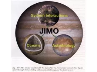
EJSM Synergistic Science • All points are designed to illustrate the value of passive radio and plasma wave measurements on both JEO and JGO • Satellite-magnetosphere interactions • Io • Ganymede • Europa • Synergistic two-point measurements in the magnetosphere • Galileo-Cassini example • Thermal plasma measurements • Passive wave measurements can provide among the most accurate plasma density measurements • Support for subsurface sounding • Monitor Jovian radio emission activity • In situ plasma density • Other measurements of interest • Dust flux and size distribution • Lightning detection
Satellite Interactions • Galileo plasma wave observations led to discovery of Ganymede’s magnetosphere • Identification of upper hybrid resonance band provides plasma density • Galilean satellites all show strong interactions with Jupiter’s magnetosphere • Plasma wave spectrum provides evidence of wave-particle interactions and the flow of mass and energy resulting from the magnetospheric interaction.
Synergistic Two-Point Measurements • Galileo – Cassini radio and plasma wave measurements revealed the response of the Jovian magnetosphere to variations in the solar wind. • Two-point measurements can help distinguish between global magnetospheric dynamics and spatial variations. • Approach solar wind observations provide valuable solar wind input for comparison with magnetospheric observations. • Magnetospheric observations by one spacecraft provides a baseline for other spacecraft in orbit (or flying by) a Galilean satellite. • Jovian radio emission monitoring provides a measure of magnetospheric activity for other spacecraft orbiting (or flying by) a Galilean satellite.
Thermal Plasma Measurements • A plasma wave instrument provides accurate plasma density measurements, a fundamental parameter of the Jovian environment and essential to many modeling efforts. • Identification of various resonances (upper hybrid) or cutoffs (electron plasma frequency, L=0, or R-X cutoff frequencies. • Quasi-thermal noise spectroscopy • Invaluable for calibration of plasma instruments.
Support for Subsurface Radar Sounders • Provides monitor for Jovian radio emission activity at sounder frequencies • Provides measurement of local plasma densities (plasma frequencies) in vicinity of Galilean satellites. Some of these are close to possible sounding frequencies. Maximum Ionospheric Densities and Plasma Frequencies • Callisto1 17,400 cm-3 1.2 MHz • Ganymede2 400 cm-3 180 kHz • Europa3 9,000 cm-3 900 kHz • Io4 277,000 cm-3 4.7 MHz • 1Kliore et al., JGR, 2002. • 2Eviatar et al., PSS, 2001. • 3Kliore et al., Science, 1997. • 4Hinson et al., JGR, 1998.
Other Measurements Possible with a Plasma Wave Instrument • Detection of lightning-generated whistlers provides evidence of atmospheric lightning. • Micron-sized dust impacting the spacecraft at several km/sec creates an impulse in a plasma wave receiver that allows an estimate of the dust flux as well as the size distribution.
Summary • Passive radio and plasma wave measurements made on both JGO and JEO provide support for subsurface radar sounding investigations. • Additionally, these measurements address a wide range of objectives central to EJSM science. • The ability to make two-point measurements in and near Jupiter’s magnetosphere enable a number of new types of advances. • The existence of a ‘long’ dipole antenna makes the addition of a radio and plasma wave receiver substantially easier to accommodate. • Passive radio and plasma wave measurements can be scheduled so as to be complementary to the SSR observations.