Download

1 / 18
210 likes | 549 Vues
Lecture 13 - Introduction to the Central Processing Unit (CPU). Outcomes. What is a CPU? How are instructions prepared by the CPU before execution? What registers and operations are involved in this preparation stage? Introduce register transfer language. What are opcodes and operands?

E N D
Lecture 13 - Introduction to the Central Processing Unit (CPU)
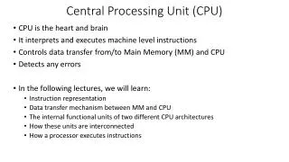
Outcomes • What is a CPU? • How are instructions prepared by the CPU before execution? • What registers and operations are involved in this preparation stage? • Introduce register transfer language. • What are opcodes and operands? • Examples of executed instructions. • Gain an understanding of the kind of processes that are performed in the CPU.
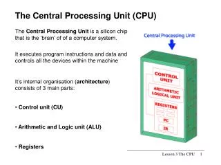
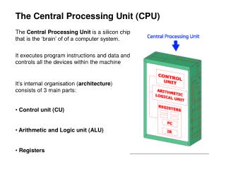
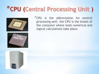
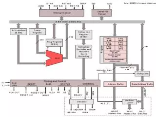
Central Processing UNIT (CPU) or Processor • ‘heart’ of the digital computer, responsible for reading a program’s instruction from memory, executing it, and then control input’s and output’s within the machine, the CPU is not usually the memory holding the instruction and the input/output devices. • What is a microprocessor is a CPU made on a single piece of semiconductor.
Fetch • Before the CPU can use an instruction, the instruction must be brought to the CPU from the memory.
Starting with a program counter (PC) this points to the next instruction to be executed. Therefore, if the contents of the PC were 5, the next instruction to be executed is stored in memory location 5. The program counter is a pointer.
The contents of the program counter are copied to the memory address register (MAR). The program counter contents are then incremented to the next instruction. The MAR holds the address of the memory location where in memory the data is to be used is located.
The contents of MAR during this part of the cycle contains address of the instruction to be executed, the contents of this memory are placed into the memory data register (MDR).
During this part of the cycle the data that is passed from memory is an instruction. • The instruction is moved from the MDR to the instruction register (IR) where it is divided into two fields.
One field is the operation code often shortened to opcode, which tells the CPU the instruction to carry out. • The second field is the operand field, which contains the address/data (or addresses) of data used by the instruction. Sometimes the operand field is not used.
RTL (Register Transfer Language) for fetch part of the cycle. • [MAR][PC] • [PC][PC]+1 • [MDR][M([MAR])] • [IR][MDR] • CU[IR(opcode)]
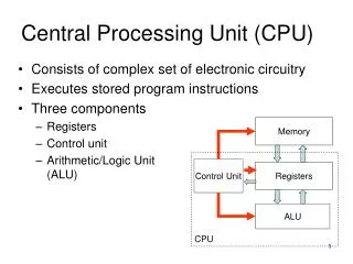
The next stage is the decode-execute cycle where the control unit takes the opcode from the instruction register, and generates the control signals to control the various parts of the CPU. The control unit is responsible during the fetch cycle for moving the contents of the PC to the MAR, executing a read cycle, and moving the contents of the MDR to the IR.
Execution Examples After the instruction has been performed we are into the execute part of the cycle, which is dependent on the instruction.
Ld A,4 Move the contents of memory location 4 to register A. [MAR][IR(operand)] The operand is transferred from the instruction register to the MAR. The Control unit performs the read operation, starting with buffering the contents stored in memory location 4 in the MBR.
[MDR][M([MAR])] The final operation is transferring the contents of the MBR to A. [A][MDR] Once the execution stage as finished, the fetch-execute cycle can being again. The cycle for the next instruction can being.
Add 5 Add the contents of memory address 5 to the data already stored in A. [MAR][IR(operand)] As in the previous example, the operand is transferred to the MAR, and the contents of the memory location pointed by the MAR are buffered in the MBR. [MDR][M([MAR])] At this point A and MBR store the data need for this instruction. To perform the addition, a control signal is set to the Arithmetic Logic Unit (ALU) where the addition is performed.
In Parallel ALU[A] ALU[MDR] The two items of data are sent to the ALU and the result of the addition is then transferred to the A. [A]ALU
Summary • ‘heart’ of the digital computer, responsible for reading a program’s instruction from memory, executing it, and then control input’s and output’s within the machine. • Fetch part of the fetch-execute in register-transfer language • [MAR][PC] • [PC][PC]+1 • [MDR][M([MAR])] • [IR][MDR] • CU[IR(opcode)] • The fetch part is the same for all instructions. • The execute part depends on the instruction fetched