HEAVY-DUTY TRUCK - Prosource Diesel
0 likes | 27 Vues
This user manual should not be used in place of common sense. Use this equipment in a manner that is specified with the vehicle manufacturer. Understand all the test procedures before attempting to use this equipment.<br>https://prosourcediesel.com/

HEAVY-DUTY TRUCK - Prosource Diesel
E N D
Presentation Transcript
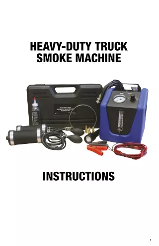
HEAVY-DUTY TRUCK SMOKE MACHINE INSTRUCTIONS 1
SAFETY: This user manual should not be used in place of common sense. Use this equipment in a manner that is specified with the vehicle manufacturer. Understand all the test procedures before attempting to use this equipment. Follow all safety precautions. • All diagnostic work should be performed with the engine off. • Do not leave the vehicle unattended when the equipment is connected or operating. • This equipment must be connected only to a fully charged 12VDC vehicle battery. WARNING: • Do not use any other type of power source to run this equipment. • Do not use this equipment near a source of spark or ignition. • Always use this equipment in a well-ventilated area. • Always wear eye protection and gloves when using this equipment. SPECIFICATIONS: • Voltage: 12 VDC • Input Pressure: Max 100 psi (7 bar) • Output Pressure: Max 28 psi (190 kPa) • Safety Pressure Relief: 120 (±5) psi • Oil Fill Line Indicator: 3.4 oz (100 ml (±10 ml) • Flow Meter: 0 - 0.040 in. (0 - 1.0 mm) • Dimensions: 11.8 x 8.1 x 11 in (300 x 205 x 280 mm) • Weight: 11.5 lbs (5.2 Kg) • Power Consumption: Max 6.5 Amps • Operating Temperature: 0˚F to 140˚F (-17˚C to 60˚C ) • Operating Humidity: No Restrictions • Operating Altitude: No Restrictions • Vapor Output Hose: 10 feet • Power Cable: 10 feet • Pressure Supply: Air/Inert gas 2
INCLUDED ACCESSORIES: 1. Two large inflatable block-off bladders with safety chains 2. 6” rigid smoke stack ring 2 3. Pressure sensor port adapter 7 4. Oxygen sensor port adapter 4 5 3 5. Temperature sensor port adapter 6 1 6. High intensity smoke illuminating battery powered flashlight 7. 8 oz smoke producing fluid 2 1 3 MACHINE COMPONENTS: 1. Smoke vapor switch 2. Smoke indicator light 3. Power source light 4. Pressure gauge 4 5 5. Pressure regulator 6. Flow meter with control knob 7. Oil fill 8. Smoke hose fitting & smoke hose cap fitting 9. Shop air/inert gas inlet 6 10. Maximum oil level 11. 12 VDC power cord connection 7 8 10 11 9 3
APPLICATION GUIDE: Leaks Evap Vacuum Oil Exhaust/Sensors Intake/Sensors Wind and Water Manifolds Turbochargers Sensors Seals & Hoses excellent suitable not supported SETUP: Connect the smoke hose: 1. Remove the smoke hose fitting cap. 2. Connect the smoke hose to the smoke hose fitting. FILL THE UNIT WITH OIL: 1. Remove the oil fill cap. 2. Open the cap from the oil bottle from the accessory box. 3. Remove the foil on top of the oil bottle. 4. Put the cap with the nozzle and red cap on the oil bottle. 5. Remove the red cap and fill the unit with oil up to the maximum oil level. NOTE: Do not over fill. NOTE: The smoke hose and a bladder with the cap removed needs to be attached in order to vent the unit to allow the oil to flow into the machine. 6. Replace the oil fill cap. 7. Store the remaining oil in the accessory box. CONNECT THE POWER CORD: 4
1. Connect the power cord to the unit. Connect the red wire with the red socket and the black wire with the black socket. 2. Connect the red clamp (+) to the positive battery terminal and connect the black clamp (-) to the chassis ground. HOW TO USE: Regulator: 1. To adjust the pressure, gently pull up the control knob. 2. Set the pressure by turning the knob. To increase the pressure, turn the knob clockwise. To decrease the pressure, turn the knob counter-clockwise. 3. To lock the pressure setting push the knob down. Intake/Exhaust Bladder: NOTE: Inspect the inside of the duct that will be tested and ensure that it is clean and free of sharp edges and burrs that could damage or puncture the bladder. 1. To use the bladder as a block off cap, install the plug on the end of the bladder. To use the bladder with smoke or air, remove the plug from the end of the bladder. 2. When working with the intake secure the bladder to engine with the lanyard and snap ring. When work- ing with an exhaust smokestack attach the ring to the lanyard and snap ring. Place the ring over the top of the smokestack. 3. Completely insert the bladder into the duct that is being tested so that both collars are inside of the duct. 4. Close the pressure relief valve by turning the knob clockwise until it is tight. 5. Compress and release the hand pump repeatedly until the bladder is secured inside the duct. 6. Ensure that the bladder is secured by gently pulling on both hoses. 7. To remove the bladder, release the pressure by turning the pressure relief knob counter-clockwise. 8. Allow the air to purge from the bladder. 9. Remove the bladder from the duct. Air/Inert Gas: 1. Open the flow meter by turning the flow control knob counter-clockwise. 2. Connect shop air or Inert gas to the quick disconnect on the back of the unit. 3. The gas will pass through the machine and into the system being tested. 4. Adjust the regulator to the proper pressure for the system that is being tested. When the pressure equalizes, the flow meter will show the size of the leak if one is present. If no leaks are present, then the ball in the flow meter will drop to the bottom of the flow meter. NOTE: Some vehicles can not be completely sealed. Smoke: 1. Pressurize the system with Air/Inert Gas. 2. Press the SMOKE button and the unit will produce smoke. To stop the production of smoke, press the SMOKE button again. Finding Leaks: 1. Once the system is pressurized with smoke, use the flashlight from the kit to search for leaks. If a leak is present the smoke will illuminate when the light passes through the smoke. 5
Leak Decay Testing: 1. Pressurize the system and set the regulator to the desired pressure. 2. Cap the pressure in the system by turning the flow meter control knob clockwise until the flow meter is closed. 3. Observe the pressure reading on the pressure gauge. If the gauge does not lose pressure then there are no leaks present. If the gauge does lose pressure then a leak exists. The flow meter will indicate the size of the leak. 4. Use the SMOKE to find the leak. 5. Repair and re-test until no more leaks are found. DIAGNOSIS: NOTE: Refer to the vehicle manufactures recommendation for the maximum pressure of each system that will be tested. Intake Leaks: 1. Disconnect the intake air duct from the air filter box. 2. Remove the cap from the end of the bladder. 3. Insert the intake/exhaust bladder that is supplied with the kit into the intake duct. 4. Attach the intake/exhaust bladder to the smoke hose quick disconnect coupling. 5. Pressurize the system with Air/Inert Gas.. 6. Press the SMOKE button. 7. Use the flashlight to locate any leaks. NOTE: Some vacuum hoses may need to be capped to find small or to isolate leaks. NOTE: Some intakes may not be 100 percent sealed by design. 8. Repair and re-test until no more leaks are found. Exhaust Leaks: 1. Remove the cap from the end of the bladder. 2. Insert the intake/exhaust bladder that is supplied with the kit into the smokestack or exhaust tailpipe. 3. Pressurize the exhaust system with Air/Inert Gas. 4. Press the SMOKE button. 5. Use the flashlight to locate any leaks. NOTE: Exhaust leaks are easier to find when the exhaust system is at ambient temperature. 6. Repair and re-test until no more leaks are found. MAINTENANCE: Cleaning the Flow Meter: 1. Disconnect the unit from the power supply. 2. Disconnect the unit from external Air/Inert Gas source. 3. Remove the screw from the bottom of the flow meter bracket. 4. Swing the flow meter out of the cabinet and unhook the bracket from the cabinet. 5. Disconnect the flow meter from the unit by disconnecting the two hoses that are attached to the back of the flow meter. 6. Remove the bracket from the back of the flow meter. 7. Remove the cap from the top of the flow meter. 8. Turn the flow meter upside down to remove the ball. 6
9. Clean the inside of the flow meter with Isopropyl alcohol and dry thoroughly. 10. Clean the ball with a dry cloth. NOTE: Do not use alcohol, cleanser or any detergent on the ball. 11. Assemble the flow meter in the reverser order. 12. Reinstall the flow meter into the machine in the reverse order. NOTE: The blue hose is attached to the top of the flow meter. The red hose is attached to the bottom of the flow meter. Draining the Smoke Hose: 1. Disconnect the unit from the power supply. 2. Disconnect the unit from external Air/Inert Gas source. 3. Disconnect the smoke hose from the back of the machine. 4. Hang the hose in a vertical position with the quick disconnect at the top. Place a container under the smoke hose. 5. Allow the excess oil to drain out of the smoke hose. 6. Reinstall the smoke hose. TROUBLESHOOTING: Problem Solution No Power Light Ensure that the power is properly Connected No Air Flow • Open the flow control valve • Check that the hoses are not kinked or pushed into machine Not Enough Smoke • Check the fluid level • Open the flow control valve clockwise • Check that the hoses are not kinked or pushed into machine • Check the smoke light, if light is off press the smoke button. • Turn the unit off. Wait 10 -20 minutes then start again. Poor Smoke Density or Volume • Insufficient smoke producing fluid: Refill • Flow control valve is partially closed • Smoke output hose is kinked High Test Pressure Reading Smoke output hose is kinked 7
For parts or service contact the service department: 1-888-825-6989 WARNING: Cancer and Reproductive Harm – www.P65Warnings.ca.gov 8 43060-HD-INST